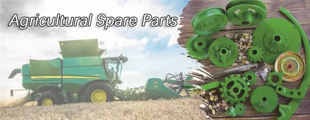
Product Description
Agricultural Lawn Mower Gearbox
Ever-power is committed to the research and development of D, spiral bevel gearboxes, spur gearboxes, worm gearboxes, cylindrical gearboxes and other gearboxes, reducers, and construction machinery manufacturing. Its products are widely used in agricultural lawn mowers, snow blowers, fertilizer spreaders, grain conveyors, industrial equipment, oil extraction machinery, marine industrial equipment, engineering hydraulic components and other fields. More than 95% of its products are exported to Europe, the United States and Australia. Asia and Canada. The company has strong technical and R&D capabilities, produces reliable and high-quality products, pursues a unique business philosophy, and enjoys a high reputation in the manufacturing industry. Welcome to contact us by phone or email.
|
ITEM |
EP-140 |
|
Ratio |
1:1.5/1:1.93 |
|
Teeth |
21/14 27/14 |
|
Module |
5.7 /5.64 |
|
Power(HP) |
60 |
|
Rated Input |
540rpm |
|
Input/Output Description |
1-3/8 Z6 Taper spline |
|
Weight(N.W) |
30KG |
Since the transmission plays such an important role in handling speed, it’s also an important part of making sure your lawnmower has the right torque for the most challenging backyard conditions:
wet grass
muddy ground
Hills and slopes (we recommend not using a riding lawn mower on slopes over 15 degrees)
Obstacles such as narrow corners, roots, and trees
A lower gear might provide more traction, but not as fast, and vice versa. Also, different transmissions have different gear
reduction ratios and different numbers of gears.
We Also Supply PTO Shafts
product-group/VqTESwWofuhM/PTO-Shaft-catalog-1.html
Other gearboxes
HangZhou Ever-power Transmission Machinery Co., Ltd. was established in 2006. The company is located in ZHangZhoug HangZhou, with 90 employees, an area of 3800 meters, and an annual output value of 40 million yuan. The company is committed to the R & D,manufacturing, and personnel training of various gearboxes, reducers, and construction machinery, including spiral bevel gearbox,spur gearbox, worm gearbox, and cylindrical gearbox. It also includes a variety of high-pressure cast valve body and shell products. Its products are used in various applications, such as agricultural mowers, snow sweepers, fertilizer applicators, grain conveyors, industrial equipment, oil mining machinery, marine industrial equipment, and engineering hydraulic components. More than 95% of its products are exported to Europe, the United States, and Australia. Asia and Canada. The company has strong technology and R & D capabilities, produces reliable and high-quality products, pursues a unique business philosophy and enjoys a high reputation in the manufacturing industry. Welcome to contact us by phone or email.
Company Information
| Type: | Agricultural |
|---|---|
| Usage: | Agricultural Products Processing, Farmland Infrastructure, Tillage, Harvester, Planting and Fertilization, Grain Threshing, Cleaning and Drying |
| Material: | Iron |
| Power Source: | Electricity |
| Weight: | 30kg |
| After-sales Service: | Installation Guide 3-Year Warranty |
Choosing the Right Agricultural Gearbox
When buying an agricultural gearbox, there are a few things to consider. The quality of materials, functionality, and mechanism are crucial factors to durability. A durable device will ensure that you won’t have to keep replacing it. Here are some tips to help you select the right one. Let’s begin. Read on to learn more about the different features available in agricultural gearboxes. Listed below are a few of the most important factors to consider.
Bevel gearboxes
Agricultural gearboxes are essential to the entire food cycle. If your gears are not in good shape, you will be unable to meet the demand and you will suffer from heightened downtime. Fortunately, there are numerous quality bevel gearboxes available on the market today. In fact, the CZPT Gearbox Company supplies bevel gearboxes for agricultural applications. Here are some of the reasons you should choose the right one.
A bevel gearbox is a single-stage unit that interlocks bevelled edges on two gears to transfer torque and rotation. These gears can be either straight or helical. This type of gearbox is inexpensive to produce and operates quietly. It also has lower transmittable torque. Bevel gearboxes are often used as a low-cost alternative to hypoid gearboxes.
Agricultural bevel gearboxes are used in various applications, including hay balers, combine harvesters, seeders, and plows. These gears are well-suited for use with offset rotary fillers. They offer reduction ratios of up to 2.44 and cast iron cases. They are commonly known as “right-angle gearboxes” or “Parallel SHAFT gearboxes.”
Agricultural bevel gearboxes come in many sizes and ratios. In general, higher sizes are made of closed-grain cast-iron. Other materials, such as SG 500/7, are used for larger sizes. The main gear and each drive gear are mesh-mounted, and the shafts are designed to rotate in either direction. They have oil seals on the joints. The Spiral Bevel Gearbox is best suited for FG60 or FG75 motors.
The RINV-OP65 right-angle angular gearbox comes with an optional electronic or mechanical position indicator. Its angular design allows for changes in axis rotation, and provides smooth power transmission with minimal backlash. Premium gearmotors include hardened spiral bevel gears and stainless steel shafts for quiet operation. They are available in various ratios and shaft styles. If you want to choose one, make sure it is made to fit the needs of the machine.
Closed-loop seals
There are a number of reasons to install closed-loop seals in an agricultural gearbox. The first is the need to isolate the gearbox from the atmosphere, an important safety concern. Closed-loop seals are CZPT alternatives to desiccant breathers because they prevent the entry of water. While these seals can’t keep the gearbox underwater, they isolate the gearbox from the atmosphere and are therefore vital for the safety of your equipment.
The most common material used for these seals is polymer rubber. Most are made from HBR, which stands for High-cis polybutadiene rubber. Other materials include Butadiene and FKM, which are known for their high-temperature performance. However, the disadvantage of these seals is that they are susceptible to shaft damage and degrade quickly in high temperatures. Therefore, you should always consider the type of seal before purchasing one.
If you plan to use agricultural gearboxes on a regular basis, you should consider getting a good quality one. You should look for a closed-loop seal on your gearbox to protect it against dirt and debris. A quality agricultural gearbox also has an easy-access design, which will make it easy to access and maintain. This will ensure its long-lasting performance and low-maintenance costs.
Agricultural equipment is frequently used to perform various tasks, such as sowing seeds, spreading fertilizer, digging holes, and more. This requires durable and effective sealing solutions to keep dirt out of the system and lubricants in. A close-loop seal helps to ensure that all these operations are performed at maximum efficiency. If you’re a farmer, closed-loop seals are the ideal solution for you.
Surface finish
The surface finish of an agricultural gearbox should be free from defects in the casting process and mechanical damage. The bearing hole in the shaft must be a minimum of 100 mm long and the distance between the bearing holes should be equal to the shaft length. The shaft should be free of any cracks or burrs. The ellipticity and centerline irregularity of the shaft must be less than 0.015 mm. Likewise, the diameter of the shaft, hole spacing and bearing hole relationship should be at least 20 mm.
In recent studies, researchers have investigated the efficiency of different surfaces on the same materials. They found that surface roughness affects gearbox efficiency. Kahraman et al. reported that superfinishing the gears and reducing surface roughness improved efficiency. In addition, Andersson et al. investigated the impact of different assembly processes on the gearbox’ surface roughness. The results of their studies are presented in Table I.
The quality of the surface finish of an agricultural gearbox depends on the materials used. A typical example is wrought steel gear. The die inserts for a forged gear were made of H11 or H13 tool steel. This material softens over time and has a limited life span. An improved alternative was Alloy 718. This alloy has a high temperature range and is suitable for high rotational speeds.
A good surface finish is vital for the health and safety of an agricultural gearbox. It protects the entire food chain and is necessary for agricultural production. The heightened demand for food will cause increased wear and tear on farm machinery. Moreover, a damaged gear will cost the farmer a lot of money. Therefore, it is crucial for farmers to invest in a high-quality agricultural gearbox to avoid such costly downtimes.
Shaft arrangement
An agricultural gearbox has two main stages, the first of which is the reduction stage. The reduction stage contains the pinion, a series of gears, and the first reduction stage. A second stage is connected to the first reduction stage via a mechanical clutch. This gearbox typically consists of three stages. The first reduction stage is also known as the low gear “L”. The first reduction stage provides four forward gearing ratios, while the second stage has three forward gearing ratios. A conventional agricultural gearbox also incorporates a mechanical clutch.
The second stage is a speed change gearbox. It has an input and output shaft. The input shaft is rotatably mounted in the casing and extends through the tractor’s interior. The shaft extends to the rear of the tractor, where the driven part of the joint 26 is keyed onto. The rear end portion of the shaft projects into the back axle casing 15, where it is connected to the first transmission shaft 34. The gearbox then serves to drive the power take-off shaft 36.
Newer types of tractors have larger shafts to support higher power applications. Type 3 tractors have a larger shaft with 20 splines while Type 2 tractors have a smaller shaft. The Type 2 is often referred to as the small 1000. When viewed from inside the tractor cab, Type 3 and Type 2 are rotated counterclockwise. If you are unfamiliar with agricultural gearboxes, here are some basic terms.
Shaft arrangement is important in choosing the right gearing system for agricultural machinery. There are a few differences between these arrangements. The first type has a higher gear ratio, while the second has lower. In terms of speed, the shaft arrangement of an agricultural gearbox reflects the speed of the machinery. The higher the speed of the gear, the higher the output speed. So, when choosing a gearbox, keep this in mind.
Cost
Purchasing an agricultural gearbox may be a costly process, but the benefits outweigh the price. Agricultural gearboxes are vital to the food cycle. When a gear breaks down, farmers will face significant losses. Additionally, agricultural applications use a high-quality gearbox to minimize equipment wear and tear. Ultimately, a high-quality gearbox will reduce the cost of production while extending the lifespan of the agricultural machinery.
Many countries trade in Agriculture Gearbox with India, and many of these suppliers are located in India. Using a marketplace to buy from Indian suppliers offers several advantages. Among the many factors to consider when choosing an Agriculture Gearbox supplier are quality, price, reliability, and past trade history. Through a marketplace like CZPT, you can obtain 360-degree information on Indian Agriculture Gearbox suppliers. In this way, you can choose a vendor with whom you do business.
CZPT Gearbox Company is a leading manufacturer of high-quality agricultural gearboxes. Their experienced engineers can reverse-engineer an existing design for a custom-made gearbox for your needs. Whether you need a smaller or larger gearbox for an agricultural application, CZPT Gearbox Company is your partner. A line of high-quality agricultural gearboxes from CZPT Gearbox Company will help you maximize the performance of your farm machinery. They will transfer rotational power from the input shaft to the output shafts, allowing for a change in speed, direction, and rotation.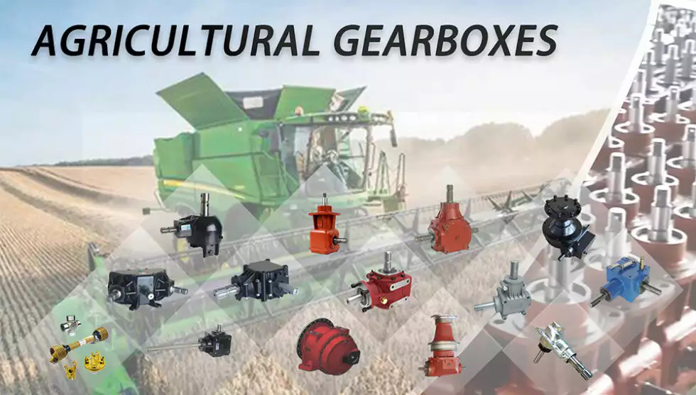
editor by CX 2023-11-09
China Epo1-672 Competitive Price Agricultural Gearbox Lawn Mower Series farm tractor transmission types
Product Description
EPO1-672 Competitive price Agricultural gearbox Lawn mower series
When choosing the right mower, there are 2 basic types: manual transmission and hydrostatic transmission. This article will compare these 2 types of transmissions and explain their effects on the mower. Which type of transmission is more suitable for your needs? Gearbox mowers are generally more fuel efficient than manual mowers. The following are other factors to consider when buying a lawnmower. This will help you decide which type is best for you.
Hydrostatic transmission
The hydrostatic transmission is a kind of transmission in lawnmower, which uses fluid to transmit power from the engine to the wheels. This transmission has the advantages of infinite speed control, self overload protection, high power-to-weight ratio, and dynamic braking. It is also reversible, allowing you to turn the mower backward. The hydrostatic transmission is usually controlled by a foot pedal, handle or cruise control device.
Hydrostatic drives in mowers are generally easy to maintain and provide a wide range of speeds. Hydrostatic transmission has a compact structure, fast response, and easy direction change. You may need to add a few ounces of oil each year to prevent rust. However, hydrostatic mowers are not without potential problems. To avoid them, please check these tips for the hydrostatic mower. You may also need to replace the old oil with high-quality hydrostatic oil. The working principle of hydrostatic transmission is very similar to that of automatic transmission. Hydraulic oil transfers energy from the engine to the drive wheels instead of using an electric motor to shift gears. The hydrostatic transmission device is composed of a pump and a motor. The pump pushes the pressurized oil through the piston in the drive system to transfer energy to the drive wheels. Compared with a standard manual transmission, hydrostatic transmission has many advantages. These mowers require less maintenance and are faster than manual mowers.
The hydrostatic transmission in the mower gearbox provides the maximum speed range, which is essential for large lawns. A disadvantage of this transmission type is that it is more expensive than a manual transmission and has lower power efficiency. However, the hydrostatic mower can help you push the mower in both directions without damaging the pump. They also do not require a clutch, which ensures smooth driving and control.
Manual transmission
Several factors to consider when selecting a manual transmission for a mower. First, consider the type of terrain you mow. Some of the terrains are rocky, steep, or slippery. You can decide which type of transmission is best for your terrain by remembering the terrain and how often you need to mow. The manual transmission will also ensure smooth driving. But how do you choose the right one?
The hydrostatic transmission is a manual transmission. The motor is powered by the fluid system, and the amount of fluid sent to the engine determines the speed. Hydrostatic mowers generally have rods controlling the fluid sent to the drive motor. The lever needs to be moved forward to start moving forward and backward to travel in reverse. These 2 types have different characteristics. Some of them are more expensive than others but easier to use.
|
PRODUCT PARAMETERS |
|
|
ITEM |
EPO1-672 |
|
Ratio |
1.92:1/1.47:1 |
|
Teeth |
23/12/22/15 |
|
Module |
5.5/5.65 |
|
Power(HP) |
50 |
|
Rated Input |
540 rpm |
|
Input/Output Description |
13/8Z6/Optic axis |
|
Weight(N.W) |
18.5Kg |
Application of mower gearbox
The manufacturers replace OEM gearboxes on 5 ‘, 6’, and 7 ‘rotary cutters: work saver, hawking, international, WAC, giant bee, LMC, King Kutter, Midwest, servis, Bush hog, Howse, etc. Please check whether the size is suitable.
Usage Scenario of Lawn Mower Gearbox
We Also Supply PTO Shaft
other gearboxes
Agricultural Gearbox Production Workshop
HangZhou Ever-power Transmission Machinery Co., Ltd. was established in 2006. The company is located in ZHangZhoug HangZhou, with 90 employees, an area of 3800 meters, and an annual output value of 40 million yuan. The company is committed to the R & D, manufacturing, and personnel training of various gearboxes, reducers, and construction machinery, including spiral bevel gearbox, spur gearbox, worm gearbox, and cylindrical gearbox. It also includes a variety of high-pressure cast valve body and shell products. Its products are used in various applications, such as agricultural mowers, snow sweepers, fertilizer applicators, CZPT conveyors, industrial equipment, oil mining machinery, marine industrial equipment, and hydraulic engineering components. More than 95% of its products are exported to Europe, the United States, and Australia. Asia and Canada. The company has robust technology and R & D capabilities, produces reliable and high-quality products, pursues a unique business philosophy, and enjoys a high reputation in the manufacturing industry. Welcome to contact us by phone or email.
HangZhou Ever-power Transmission Machinery Co., Ltd. was established in 2006. The company is located in ZHangZhoug HangZhou, with 90 employees, an area of 3800 meters, and an annual output value of 40 million yuan. The company is committed to the R & D, manufacturing, and personnel training of various gearboxes, reducers, and construction machinery, including spiral bevel gearbox, spur gearbox, worm gearbox, and cylindrical gearbox. It also includes a variety of high-pressure cast valve body and shell products. Its products are used in various applications, such as agricultural mowers, snow sweepers, fertilizer applicators, CZPT conveyors, industrial equipment, oil mining machinery, marine industrial equipment, and hydraulic engineering components. More than 95% of its products are exported to Europe, the United States, and Australia. Asia and Canada. The company has robust technology and R & D capabilities, produces reliable and high-quality products, pursues a unique business philosophy, and enjoys a high reputation in the manufacturing industry. Welcome to contact us by phone or email.
|
US $85-99 / Piece | |
100 Pieces (Min. Order) |
###
| Application: | Motor, Electric Cars, Motorcycle, Machinery, Marine, Agricultural Machinery, Car |
|---|---|
| Function: | Distribution Power, Clutch, Change Drive Torque, Change Drive Direction, Speed Changing, Speed Reduction, Speed Increase |
| Layout: | Coaxial |
| Hardness: | Hardened Tooth Surface |
| Installation: | Horizontal Type |
| Type: | Agricultural Gearbox |
###
| Samples: |
US$ 9999/Piece
1 Piece(Min.Order) |
|---|
###
|
PRODUCT PARAMETERS
|
|
|
ITEM
|
EPO1-672
|
|
Ratio
|
1.92:1/1.47:1
|
|
Teeth
|
23/12/22/15
|
|
Module
|
5.5/5.65
|
|
Power(HP)
|
50
|
|
Rated Input
|
540 rpm
|
|
Input/Output Description
|
13/8Z6/Optic axis
|
|
Weight(N.W)
|
18.5Kg
|
|
US $85-99 / Piece | |
100 Pieces (Min. Order) |
###
| Application: | Motor, Electric Cars, Motorcycle, Machinery, Marine, Agricultural Machinery, Car |
|---|---|
| Function: | Distribution Power, Clutch, Change Drive Torque, Change Drive Direction, Speed Changing, Speed Reduction, Speed Increase |
| Layout: | Coaxial |
| Hardness: | Hardened Tooth Surface |
| Installation: | Horizontal Type |
| Type: | Agricultural Gearbox |
###
| Samples: |
US$ 9999/Piece
1 Piece(Min.Order) |
|---|
###
|
PRODUCT PARAMETERS
|
|
|
ITEM
|
EPO1-672
|
|
Ratio
|
1.92:1/1.47:1
|
|
Teeth
|
23/12/22/15
|
|
Module
|
5.5/5.65
|
|
Power(HP)
|
50
|
|
Rated Input
|
540 rpm
|
|
Input/Output Description
|
13/8Z6/Optic axis
|
|
Weight(N.W)
|
18.5Kg
|
What Is a Gearbox?
There are several factors to consider when choosing a gearbox. Backlash, for example, is a consideration, as it is the angle at which the output shaft can rotate without the input shaft moving. While this isn’t necessary in applications without load reversals, it is important for precision applications involving load reversals. Examples of these applications include automation and robotics. If backlash is a concern, you may want to look at other factors, such as the number of teeth in each gear.
Function of a gearbox
A gearbox is a mechanical unit that consists of a chain or set of gears. The gears are mounted on a shaft and are supported by rolling element bearings. These devices alter the speed or torque of the machine they are used in. Gearboxes can be used for a wide variety of applications. Here are some examples of how gearboxes function. Read on to discover more about the gears that make up a gearbox.
Regardless of the type of transmission, most gearboxes are equipped with a secondary gear and a primary one. While the gear ratios are the same for both the primary and secondary transmission, the gearboxes may differ in size and efficiency. High-performance racing cars typically employ a gearbox with two green and one blue gear. Gearboxes are often mounted in the front or rear of the engine.
The primary function of a gearbox is to transfer torque from one shaft to another. The ratio of the driving gear’s teeth to the receiving member determines how much torque is transmitted. A large gear ratio will cause the main shaft to revolve at a slower speed and have a high torque compared to its counter shaft. Conversely, a low gear ratio will allow the vehicle to turn at a lower speed and produce a lower torque.
A conventional gearbox has input and output gears. The countershaft is connected to a universal shaft. The input and output gears are arranged to match the speed and torque of each other. The gear ratio determines how fast a car can go and how much torque it can generate. Most conventional transmissions use four gear ratios, with one reverse gear. Some have two shafts and three inputs. However, if the gear ratios are high, the engine will experience a loss of torque.
In the study of gearbox performance, a large amount of data has been collected. A highly ambitious segmentation process has yielded nearly 20,000 feature vectors. These results are the most detailed and comprehensive of all the available data. This research has a dual curse – the first is the large volume of data collected for the purpose of characterization, while the second is the high dimensionality. The latter is a complication that arises when the experimental gearbox is not designed to perform well.
Bzvacklash
The main function of a gearhead is to multiply a moment of force and create a mechanical advantage. However, backlash can cause a variety of issues for the system, including impaired positioning accuracy and lowered overall performance. A zero backlash gearbox can eliminate motion losses caused by backlash and improve overall system performance. Here are some common problems associated with backlash in gearheads and how to fix them. After you understand how to fix gearbox backlash, you’ll be able to design a machine that meets your requirements.
To reduce gearbox backlash, many designers try to decrease the center distance of the gears. This eliminates space for lubrication and promotes excessive tooth mesh, which leads to premature mesh failure. To minimize gearbox backlash, a gear manufacturer may separate the two parts of the gear and adjust the mesh center distance between them. To do this, rotate one gear with respect to the fixed gear, while adjusting the other gear’s effective tooth thickness.
Several manufacturing processes may introduce errors, and reducing tooth thickness will minimize this error. Gears with bevel teeth are a prime example of this. This type of gear features a small number of teeth in comparison to its mating gear. In addition to reducing tooth thickness, bevel gears also reduce backlash. While bevel gears have fewer teeth than their mating gear, all of their backlash allowance is applied to the larger gear.
A gear’s backlash can affect the efficiency of a gearbox. In an ideal gear, the backlash is zero. But if there is too much, backlash can cause damage to the gears and cause it to malfunction. Therefore, the goal of gearbox backlash is to minimize this problem. However, this may require the use of a micrometer. To determine how much gearbox backlash you need, you can use a dial gauge or feeler gauge.
If you’ve been looking for a way to reduce backlash, a gearbox’s backlash may be the answer. However, backlash is not a revolt against the manufacturer. It is an error in motion that occurs naturally in gear systems that change direction. If it is left unaccounted for, it can lead to major gear degradation and even compromise the entire system. In this article, we’ll explain how backlash affects gears and how it affects the performance of a gearbox.
Design
The design of gearboxes consists of a variety of factors, including the type of material used, power requirements, speed and reduction ratio, and the application for which the unit is intended. The process of designing a gearbox usually begins with a description of the machine or gearbox and its intended use. Other key parameters to consider during gearbox design include the size and weight of the gear, its overall gear ratio and number of reductions, as well as the lubrication methods used.
During the design process, the customer and supplier will participate in various design reviews. These include concept or initial design review, manufacturing design validation, critical design review, and final design review. The customer may also initiate the process by initiating a DFMEA. After receiving the initial design approval, the design will go through several iterations before the finalized design is frozen. In some cases, the customer will require a DFMEA of the gearbox.
The speed increaser gearboxes also require special design considerations. These gearboxes typically operate at high speeds, causing problems with gear dynamics. Furthermore, the high speeds of the unit increase frictional and drag forces. A proper design of this component should minimize the effect of these forces. To solve these problems, a gearbox should incorporate a brake system. In some cases, an external force may also increase frictional forces.
Various types of gear arrangements are used in gearboxes. The design of the teeth of the gears plays a significant role in defining the type of gear arrangement in the gearbox. Spur gear is an example of a gear arrangement, which has teeth that run parallel to the axis of rotation. These gears offer high gear ratios and are often used in multiple stages. So, it is possible to create a gearbox that meets the needs of your application.
The design of gearboxes is the most complex process in the engineering process. These complex devices are made of multiple types of gears and are mounted on shafts. They are supported by rolling element bearings and are used for a variety of applications. In general, a gearbox is used to reduce speed and torque and change direction. Gearboxes are commonly used in motor vehicles, but can also be found in pedal bicycles and fixed machines.
Manufacturers
There are several major segments in the gearbox market, including industrial, mining, and automotive. Gearbox manufacturers are required to understand the application and user industries to design a gearbox that meets their specific requirements. Basic knowledge of metallurgy is necessary. Multinational companies also provide gearbox solutions for the power generation industry, shipping industry, and automotive industries. To make their products more competitive, they need to focus on product innovation, geographical expansion, and customer retention.
The CZPT Group started as a small company in 1976. Since then, it has become a global reference in mechanical transmissions. Its production range includes gears, reduction gearboxes, and geared motors. The company was the first in Italy to achieve ISO certification, and it continues to grow into one of the world’s leading manufacturers of production gearboxes. As the industry evolves, CZPT focuses on research and development to create better products.
The agriculture industry uses gearboxes to implement a variety of processes. They are used in tractors, pumps, and agricultural machinery. The automotive industry uses gears in automobiles, but they are also found in mining and tea processing machinery. Industrial gearboxes also play an important role in feed and speed drives. The gearbox industry has a diverse portfolio of manufacturers and suppliers. Here are some examples of gearboxes:
Gearboxes are complex pieces of equipment. They must be used properly to optimize efficiency and extend their lifespan. Manufacturers employ advanced technology and strict quality control processes to ensure their products meet the highest standards. In addition to manufacturing precision and reliability, gearbox manufacturers ensure that their products are safe for use in the production of industrial machinery. They are also used in office machines and medical equipment. However, the automotive gearbox market is becoming increasingly competitive.


editor by czh 2022-11-27
China supplier CE Certified Verge Flail Mower with Hydraulic Side Shift Pto Drive for Tractor near me factory
Product Description
| Model | EFGCH-105M | EFGCH-115M | EFGCH-125M | EFGCH-135M | EFGCH-145M |
| Structure Weight | 285kg | 300kg | 312kg | 327kg | 352kg |
| Working Width | 1571mm | 1120mm | 1220mm | 1320mm | 1420mm |
| PTO Turning Speed | 540r/min | 540r/min | 540r/min | 540r/min | 540r/min |
| Flail Type | Y Blade / Hammer | ||||
| Number Of Flails | Hammer: 18 / Y Blade: 36 | Hammer: 18 / Y Blade: 36 | Hammer: 18 / Y Blade: 36 | Hammer: 22 / Y Blade: 44 | Hammer: 22 / Y Blade: 44 |
| Tractor HP | 18-25hp | 15-25hp | 18-25hp | 20-30hp | 30-35hp |
| Shift Distance | 170mm | 170mm | 348mm | 348mm | 348mm |
| Model | EFGCH-155M | EFGCH-165M | EFGCH-175M | EFGCH-185M | EFGCH-195M |
| Structure Weight | 332kg | 347kg | 359kg | 385kg | 412kg |
| Working Width | 1520mm | 1620mm | 1720mm | 1820mm | 1920mm |
| PTO Turning Speed | 540r/min | 540r/min | 540r/min | 540r/min | 540r/min |
| Flail Type | Y Blade / Hammer | ||||
| Number Of Flails | Hammer: 22 / Y Blade: 44 | Hammer: 26 / Y Blade: 52 | Hammer: 26 / Y Blade: 52 | Hammer: 32 / Y Blade: 64 | Hammer: 32 / Y Blade: 64 |
| Tractor HP | 30-40hp | 35-45hp | 40-50hp | 45-85hp | 45-85hp |
| Shift Distance | 348mm | 348mm | 348mm | 348mm | 348mm |
Our description :1. Adjustable to meet various height requirements
2. Deck plate thickness 5/32inch (4mm)
3. Side plate thickness 15/64inch (6mm)
4. 3-PTO shear pin shaft category 1 & 2 hookup
5. Durable high-quality powder spray painting
6. With hydraulic system
our advantage:A whole complete set of production equipment lead to short lead time and better prices of machine.
Guarantee 1 year warranty of all our products.
Produce machines according to any requirements from our customers.
New machines will be developed every year.
Every model of our machine will be tested before the delivery to the port.
If you want to visit our factory, our boss will give you a best reception.
Supporting Ball Screws
In order to use a ball screw in a project, it is important to support it for rotation. Typically, this requires holding brackets and roller bearings. Longer screws may require bending or critical speed restraints. End machining may be necessary to fit the screw into the bearing. Connection to a motor requires coupling and appropriate machining. Tables or support rails may be necessary to restrain the nut.
Cost
In this report, you’ll get an in-depth analysis of the ball screw market. You’ll learn about the competitive landscape, product portfolio, and growth prospects across regions. The report will also include information on the market’s various drivers and restraints, as well as the factors driving or restraining its development. You’ll also get an in-depth look at the value chain and PEST analysis, which are important components of a market study.
One resource that you can use to research the Ball Screw market is CZPT. This website contains a database of authentic Indian manufacturers, suppliers, and importers. You’ll find contact details and email addresses of the companies, including those that produce a wide variety of different types of ball screws. CZPT even allows you to search by product category. That way, you can find a supplier based on the type of ball screw you need at the lowest price.
Another benefit of ball screws is their ability to operate in very delicate applications. In electric vehicles, they are often used to replace a common hydraulic system. They are also used to control gates at hydroelectric stations. You can also find them in motorised inspection tables, step photolithography machines, and microscopic integrated circuits. You can find hundreds of different ball screw designs, and you can even purchase them with nuts, wipers, and CZPT. Ball screws have several bearing balls, which help transfer load between nut and screw. They can be available with adjustable preload and non-preloaded options. And they’re manufactured to industry standards to meet the demands of their users.
If you’re looking for a reliable, high-performing screw, you’ll want to opt for a ball screw. These have high performance-to-cost ratios. You’ll need to choose between a lead screw and a ball screw, but both are reliable and efficient. Besides, the former is less expensive and offers great design flexibility. They’re corrosion-resistant and can even be self-locking for vertical applications.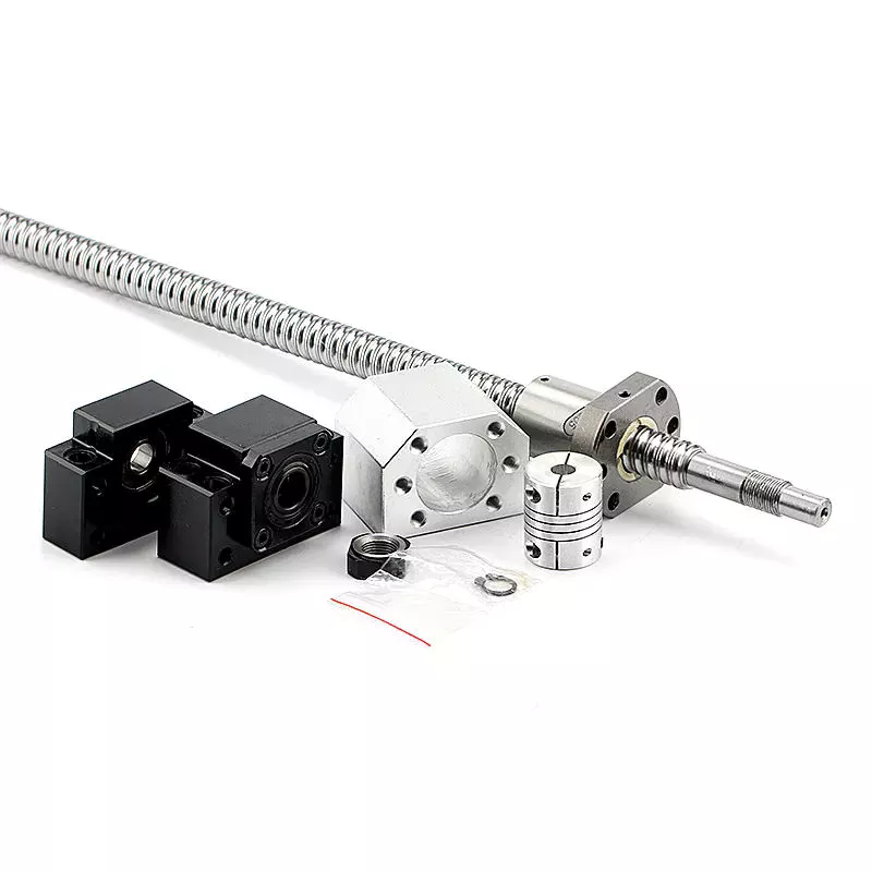
Applications
A ball screw and nut assembly are essential components of a variety of important actuation and control devices. The 2 components rely on the ability of the screw to rotate easily while converting the rotation into precise lateral movement. Ball screws are a common component in computer-controlled motion-control systems. The precision of ball screw rotation is essential for the accurate adjustment of flight control surfaces. In addition, ball screws are important components of wire bonding and computer-controlled motion-control systems.
Ball screws are highly accurate, requiring minimal lead error. The lead error of a screw is the difference between the theoretical and actual distance traveled by the nut during rotation. The lead error of a ball screw depends on several factors, including the manufacturing accuracy of the ball grooves, the compactness of the assembly, and the set-up precision. This error is not constant from lead to lead, but it may be reduced through preloading, lubrication, and increased mounting accuracy.
The ball is urged to move up and down by rotation of the nut, which is preferably a hexagonal shaft. This allows the ball to be raised easily over the land of the screw. It is important to note that the nut has a groove on the outer surface that is deep enough to accommodate a ball. This groove is deep enough to accommodate a ball, and the groove extends the length of the screw, thereby reducing friction and increasing precision.
The recirculated balls in a multi-start ball screw assembly may cross multiple threads and turn in the circuit. Multi-start ball screw assemblies typically use the internal channel method to recirculate balls. This design allows multiple ball nuts to be used in a single nut and can be easily installed. The ball nut and the nut may also be incorporated into several separate circuits. If several recirculation paths are desired, a ball nut and a multi-start system may be used.
Durability
A key feature of ball screws is their durability. During manufacture, a ball screw’s material must be chosen carefully. A corrosion-resistant steel called Cronidur(r) 30 is an ideal choice. Ball screws made from this material are exceptionally reliable in space due to their alternating steel-ceramic architecture. As the conditions of space are extreme, corrosion-resistant materials are essential to ensure optimum performance. CZPT has decades of experience manufacturing high-quality ball screws. Besides providing a complete range of ball screws, the company also offers technological solutions and dedicated components.
CZPT developed a special design for the High-Durability Precision Ball Screw. This design makes it easier to form a thin film of oil on the material’s surface. This oil helps reduce friction and improve the precision of a ball screw. This material’s special microstructure reduces the wear of ball screws and improves their service life. CZPT also aims to improve the wear-resistance of ball screws.
In addition to the axial load, a ball screw’s life rating should be based on the jacking and vertical loads. In other words, if all load balls are in contact with the raceways, the L-10 life rating of ball screw assemblies would be converted to an L-2 life rating. This change would increase the overall reliability of a ball screw to 98%. Then again, it’s important to note that vertical load is the only 1 that would be completely removed from the chart.
In addition to these important considerations, it is essential to operate ball screws within their recommended operating temperature range. Failure to do so could result in thermal expansion of the ball screw, causing positioning errors. To ensure lubrication of the ball screw, it’s important to keep its operating temperature within the recommended range. However, it is possible to operate it at temperatures that are too high. If this occurs, the screw should be sent to the manufacturer for repair.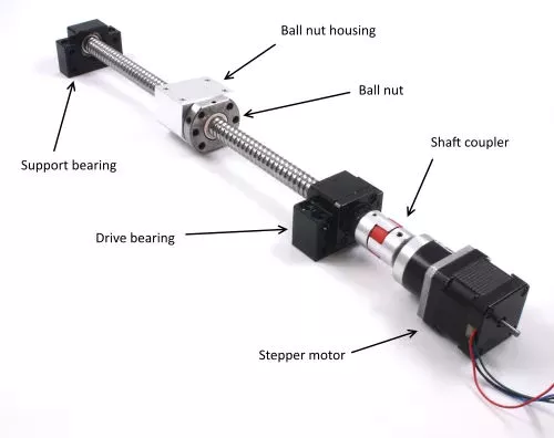
Size
Besides their obvious use, ball screws come in 2 sizes, large and small. Although small balls should not show significant wear, they should still be used to enhance the screw’s durability. This can be difficult to determine because screw rebuilders tend to overlook this aspect. So, what is the best size for ball screws? This article will look at both sizes and what they mean for the screw’s durability. Also, we’ll look at some of the things to keep in mind when choosing the right size for your project.
A ball screw’s size depends on its application and performance requirements. Some types have small diameters and fine leads, while others feature large diameters. High precision applications often require miniature ball screws. Some manufacturers even offer compact ball screws with a smaller outer diameter. The latter is commonly found in miniature designs and feature diameters up to 25 mm. However, this doesn’t mean that a smaller diameter means less accuracy. Regardless of the size, you’ll want to make sure to select a screw that will meet your requirements.
The screw’s root diameter is a critical measurement in determining critical speed and column load calculations. A ball screw’s minor diameter is the minimum dimension of the screw shaft at the bottom of the ball grooves. In addition, the idler ball is a necessary component of a ball screw. It prevents friction between the load and idler balls, but does not carry the load itself. Likewise, the non-operating load capacity should be large enough to prevent the balls from brinelling and plastic deformation.
The characteristic speed is the rotational speed at which the ball screw begins to vibrate due to dynamic load. Inch/imperial screws are specified for 1 million revolutions, while metric screw has a specific limit for 1 million inches of linear travel. Various manufacturing processes have their own ways to calculate the useful life of ball screw assemblies. For example, Precision Grinding produces the lowest lead errors. In addition, the life of a ball screw depends on the length of the screw and the mounting support for the end bearings.
Maintenance
It is critical to regularly perform PM on your ball screw assemblies to ensure optimal performance. A dirty ball screw assembly will result in poor performance and faster wear, so removing dirt from the nut and shaft is a good idea. If there are problems with the ball nut, the lubricant inside can become stripped or the nut can become dirty due to chemical exposure. You should also check for oxidation or corrosion on the contact surfaces of the ball screw, and replace it if necessary.
The first sign of a deteriorating ball screw is excessive vibration. This may be caused by a bent screw shaft or misaligned bearing housings. If it makes noise when running, this may be due to excessive build-up or a broken return tube. Other issues may be caused by endplay in support bearings or excessive preload or improper lubrication. If any of these problems are found, it is essential to perform regular maintenance on the ball screw to prolong its life.
Getting regular maintenance on the ball screw assembly is important. If the screw is not properly maintained, it may wear out prematurely. If this happens, you can contact a ball screw repair service. CZPT International, Inc., a leading supplier of industrial parts, can help you get the screw back into optimal working order or find a new one. A ball screw repair company can help you avoid the inconvenience of downtime and maximize your productivity.
It is essential to properly lubricate a ball screw assembly in order to prolong its life. Lubrication can prevent corrosion and increase the life of the screw by 85 percent. It is important to remember that the type of lubricant you use should correspond to the load applied to the assembly. Lubrication should also be done at regular intervals. Once you’ve established the right amount of lubrication, you can then apply it on the screw.


China Good quality CE Approved Side Mower Tractor Mounted Verge Flail Mower Tow Behind Grass Cutter Flail Mower for Sale near me factory
Product Description
Side Flail Mower
Main Specifications:
1. Used for the flat land grass, the weeds in the slope and bush side trimming.
2. Full dynamic balance testing before packing, to ensure the blades stability in high speed running and less noise.
3. Double Y shape blades, high cutting efficiency.
4. Bearing installed in 2 ends of roller, to make sure the flexibility of rotating and prevents hard abrasion.
5. Options for blade: (1) Y shape blade (2) Hammer
6. It can be turned in sideways. Vertical and horizontal sides.
7. With belt tension pulley device.
8. With Hydraulic system, mainly for 20-30HP tractor
|
Model |
EFDL-105 | EFD-115 | EFD-125 |
| Dimension(mm) | 1265×1355×836 | 12365*1355*835 | 1465*1355*836 |
| Weight(Kg) | 210Kg | 225KG | 240Kg |
| Cutting Width | 1050mm | 1150mm | 1250mm |
| PTO Input Speed | 540r/min | 540r/min | 540r/min |
| Y shape blades | 72 | 78 | 84 |
| Power Required | 20-25HP | 20-30HP | 20-30HP |
| 3 point linkage | Cat.1 | Cat.1 | Cat.1 |
| Packing size(mm) | 1250×750×550 | 1350*750*550 | 1450×750×550 |
Customer Case
Company Profile
HangZhou CZPT Industry & Trade Co., Ltd., is a professional manufacturer and exporter of whole set of agriculture machines and garden tools. Our company was established since 2003 with Hanma Industry Company.
Our main products include rotovator, flail mower, finishing mower, CZPT mower, wood chipper, plow, cultivator, potato harvester/ planter and Japanese tractor parts, etc. Due to our super International quality standard and rapid & excellent after-sales service, CZPT machines are greatly popular in various markets around the world, and already reached to Europe, North America, South America, Australia, almost covers 80 countries in World.
LEFA always believe that we will take better farming life to you by top-quality laser cutting machine & CNC bending machine & professional paint-spraying & strong welding.
PROFESSIONAL PRODUCTION:
1.Professional team with rich experience
2.Powerful factory strength with CE certification
3.Best after-sales service
Packing & Shipping
Packaging Detail: Iron pallet or wooden cases
Delivery Detail: By sea or By air
1. Waterproof packing with the international export standard by 20ft, 40ftcontainer.
Wooden Case or Iron Pallet.
2. The whole set of machines size are large as normal, so we will use Waterproof materials to pack
all of them. The motor, gear box or other easily damaged parts, we will put them into box.
We have a professional shipping department, they will try their best to save your container quantity.
Machine videos in YOUTOBE
EFDL SIDE MOWERS
EFGL SIDE MOWERS
FM FINISHING MOWERS
TM CZPT MOWERS
RT ROTARY TILLERS
https://youtu.be/d3H1-yXUImc AP-90 POTATO HARVESTER
https://youtu.be/AAkgnV_bY80 LF-PT32 POTATO PLANTER
https://youtu.be/66geQQOUTLY wood chipper BX-42
https://youtu.be/iIVOwCTCl_c HAY BALER
FAQ:
Q1. How to buy 3 point rotary tiller?
Inquiry ———> Quotation ——–>Price reasonable ——->Check with specification —–>Proforma Invoice sent ————>Payment made ——-> Producing the items ——->Product shipment ———–> Customer confirm
Q2.How long is the delivery date for agriculture machinery cultivator?
A:In general, we can ship the goods within 30-45 days after receiving your payment. Of course, it also depends on your quantity.
Q3. How can I get to your factory to buy tractor cultivator?
A:We are located in HangZhou, only 1 hour’s distance to ZheJiang or HangZhou. You can fly to ZheJiang /HangZhou/HangZhou Airport , the transportation is very convenient
Q4.Do you have stock for rotary tiller?
A:In general, we have some stock, while if you need a bulk order, we still need time to produce it. Of course, we will inform all details you before your payment.
Q5: What’s your main products?
A: Our products are covered almost all farm machines and Japanese tractors parts, we can meet your any demands.
Q6. What is your terms of payment?
A: T/T, L/C, Paypal, Western Union
What Are the Advantages of a Splined Shaft?
If you are looking for the right splined shaft for your machine, you should know a few important things. First, what type of material should be used? Stainless steel is usually the most appropriate choice, because of its ability to offer low noise and fatigue failure. Secondly, it can be machined using a slotting or shaping machine. Lastly, it will ensure smooth motion. So, what are the advantages of a splined shaft?
Stainless steel is the best material for splined shafts
When choosing a splined shaft, you should consider its hardness, quality, and finish. Stainless steel has superior corrosion and wear resistance. Carbon steel is another good material for splined shafts. Carbon steel has a shallow carbon content (about 1.7%), which makes it more malleable and helps ensure smooth motion. But if you’re not willing to spend the money on stainless steel, consider other options.
There are 2 main types of splines: parallel splines and crowned splines. Involute splines have parallel grooves and allow linear and rotary motion. Helical splines have involute teeth and are oriented at an angle. This type allows for many teeth on the shaft and minimizes the stress concentration in the stationary joint.
Large evenly spaced splines are widely used in hydraulic systems, drivetrains, and machine tools. They are typically made from carbon steel (CR10) and stainless steel (AISI 304). This material is durable and meets the requirements of ISO 14-B, formerly DIN 5463-B. Splined shafts are typically made of stainless steel or C45 steel, though there are many other materials available.
Stainless steel is the best material for a splined shaft. This metal is also incredibly affordable. In most cases, stainless steel is the best choice for these shafts because it offers the best corrosion resistance. There are many different types of splined shafts, and each 1 is suited for a particular application. There are also many different types of stainless steel, so choose stainless steel if you want the best quality.
For those looking for high-quality splined shafts, CZPT Spline Shafts offer many benefits. They can reduce costs, improve positional accuracy, and reduce friction. With the CZPT TFE coating, splined shafts can reduce energy and heat buildup, and extend the life of your products. And, they’re easy to install – all you need to do is install them.
They provide low noise, low wear and fatigue failure
The splines in a splined shaft are composed of 2 main parts: the spline root fillet and the spline relief. The spline root fillet is the most critical part, because fatigue failure starts there and propagates to the relief. The spline relief is more susceptible to fatigue failure because of its involute tooth shape, which offers a lower stress to the shaft and has a smaller area of contact.
The fatigue life of splined shafts is determined by measuring the S-N curve. This is also known as the Wohler curve, and it is the relationship between stress amplitude and number of cycles. It depends on the material, geometry and way of loading. It can be obtained from a physical test on a uniform material specimen under a constant amplitude load. Approximations for low-alloy steel parts can be made using a lower-alloy steel material.
Splined shafts provide low noise, minimal wear and fatigue failure. However, some mechanical transmission elements need to be removed from the shaft during assembly and manufacturing processes. The shafts must still be capable of relative axial movement for functional purposes. As such, good spline joints are essential to high-quality torque transmission, minimal backlash, and low noise. The major failure modes of spline shafts include fretting corrosion, tooth breakage, and fatigue failure.
The outer disc carrier spline is susceptible to tensile stress and fatigue failure. High customer demands for low noise and low wear and fatigue failure makes splined shafts an excellent choice. A fractured spline gear coupling was received for analysis. It was installed near the top of a filter shaft and inserted into the gearbox motor. The service history was unknown. The fractured spline gear coupling had longitudinally cracked and arrested at the termination of the spline gear teeth. The spline gear teeth also exhibited wear and deformation.
A new spline coupling method detects fault propagation in hollow cylindrical splined shafts. A spline coupling is fabricated using an AE method with the spline section unrolled into a metal plate of the same thickness as the cylinder wall. In addition, the spline coupling is misaligned, which puts significant concentration on the spline teeth. This further accelerates the rate of fretting fatigue and wear.
A spline joint should be lubricated after 25 hours of operation. Frequent lubrication can increase maintenance costs and cause downtime. Moreover, the lubricant may retain abrasive particles at the interfaces. In some cases, lubricants can even cause misalignment, leading to premature failure. So, the lubrication of a spline coupling is vital in ensuring proper functioning of the shaft.
The design of a spline coupling can be optimized to enhance its wear resistance and reliability. Surface treatments, loads, and rotation affect the friction properties of a spline coupling. In addition, a finite element method was developed to predict wear of a floating spline coupling. This method is feasible and provides a reliable basis for predicting the wear and fatigue life of a spline coupling.
They can be machined using a slotting or shaping machine
Machines can be used to shape splined shafts in a variety of industries. They are useful in many applications, including gearboxes, braking systems, and axles. A slotted shaft can be manipulated in several ways, including hobbling, broaching, and slotting. In addition to shaping, splines are also useful in reducing bar diameter.
When using a slotting or shaping machine, the workpiece is held against a pedestal that has a uniform thickness. The machine is equipped with a stand column and limiting column (Figure 1), each positioned perpendicular to the upper surface of the pedestal. The limiting column axis is located on the same line as the stand column. During the slotting or shaping process, the tool is fed in and out until the desired space is achieved.
One process involves cutting splines into a shaft. Straddle milling, spline shaping, and spline cutting are 2 common processes used to create splined shafts. Straddle milling involves a fixed indexing fixture that holds the shaft steady, while rotating milling cutters cut the groove in the length of the shaft. Several passes are required to ensure uniformity throughout the spline.
Splines are a type of gear. The ridges or teeth on the drive shaft mesh with grooves in the mating piece. A splined shaft allows the transmission of torque to a mate piece while maximizing the power transfer. Splines are used in heavy vehicles, construction, agriculture, and massive earthmoving machinery. Splines are used in virtually every type of rotary motion, from axles to transmission systems. They also offer better fatigue life and reliability.
Slotting or shaping machines can also be used to shape splined shafts. Slotting machines are often used to machine splined shafts, because it is easier to make them with these machines. Using a slotting or shaping machine can result in splined shafts of different sizes. It is important to follow a set of spline standards to ensure your parts are manufactured to the highest standards.
A milling machine is another option for producing splined shafts. A spline shaft can be set up between 2 centers in an indexing fixture. Two side milling cutters are mounted on an arbor and a spacer and shims are inserted between them. The arbor and cutters are then mounted to a milling machine spindle. To make sure the cutters center themselves over the splined shaft, an adjustment must be made to the spindle of the machine.
The machining process is very different for internal and external splines. External splines can be broached, shaped, milled, or hobbed, while internal splines cannot. These machines use hard alloy, but they are not as good for internal splines. A machine with a slotting mechanism is necessary for these operations.
China best Tractor Mower with Pto Drive Shaft Finishing Mower with Great quality
Product Description
Specifications:;
hot selling farm tractor PTO finishing mower for Europe
Style:; FM-120 -150 -180
Change color upon request
Well-known in Europe
3 point linkage
Graphite casting iron gearbox
Tractor power required:; 18-35hp
Product Attribute
1.; Transmission:; V belt transmission,; more reliable.;
2.; Graphite gearbox is made of casting iron.; Material performance is better.; Not easy broken.;
3.;3 pieces of blades are working meanwhile,; expanding the cutting width.;
4.; Blade shaft seat is made of casting iron.; More reliable and strong.;
5.; Rear-discharge and side-discharge can be selectable for you.;
6.; The wheel is clad in rubber,; more stable and wear-resistant.;
7.;Mainly for cutting grass in the flat area,; and smaller bushes or weeds below half a meter.;
8.; Mowing height can be adjusted.;
Functions:;
Detailed Product Description on Finishing Mower
Uses:;
Perfect for use when presentation is essential,; ideal for work around golf courses,; sporting fields,; parklands,; camping grounds,; schools,; homesteads and roadsides,; rear discharge for normal use or side discharge option for use in areas where the cuttings need to be thrown clear? Like under orchards.;
Features:;
Rear or side discharge options,; 4 independent height adjustable castor wheels allow the mower to contour over uneven surfaces to provide an even finish,; 3 high strength cutting blades for a more precision finish,; floating top hitch to increase surface contouring.;
Advantages of our company—HangZhou Lefa
1.; Specializing in manufacturing and selling the farm machine more than 11 years.;
2.; “Lefa” produce in China and France.;
3.; With CE certificate.;.;
4.; With the strict quality control and best service for customers.;
5.; We can provide excellent and rapid after-sales service.;
6.; Our aim:; Win-win.;
7.; We can design and produce machines according to customer’s needs.;
8.; We developed dozens of Japanese tractors parts,; we can deliver the parts with machine together.;
Co-operation Policy:;
1.; Sample Policy:; You can test the quality of our sample firstly before you purchase them in mass
Quantity.;
2.; Payment Way:; T/T,; L/C,; Western Union,; D/P.;
3.; Delivery Date:; 10-30 days after deposit paid.; It depend on your order quantity.;
4.; Shipping Way:; By Sea or By Air.;
5.; After Service:; 12 months guarantee of the main parts,; we will send the guarantee parts together with the machine in your next order or we can send them by air express if you need them urgently.;
Our Purpose:;
Quality first,; best service,; win-win!
We sincerely welcome customers abroad to visit us to discuss cooperation and seek common development.; We believe our company is your most reliable partner and friend!
| Model | Dimension(mm); | PTO (rpm); | No of Blades | Power Required | Packing Size(mm); |
| FM-120 | 1260*1200*650 | 540 | 2 or 3 | 18-25hp | 1400*760*2200 |
| FM-150 | 1570*1200*650 | 540 | 2 or 3 | 20-30hp | 1700*860*2200 |
| FM-180 | 1860*1350*650 | 540 | 2 or 3 | 20-35hp | 2000*1100*2200 |
| FM-100 | 1100*1100*700 | 540 | 2 or 3 | 16-25HP | 1200*1150*2200 |
Stiffness and Torsional Vibration of Spline-Couplings
In this paper, we describe some basic characteristics of spline-coupling and examine its torsional vibration behavior. We also explore the effect of spline misalignment on rotor-spline coupling. These results will assist in the design of improved spline-coupling systems for various applications. The results are presented in Table 1.
Stiffness of spline-coupling
The stiffness of a spline-coupling is a function of the meshing force between the splines in a rotor-spline coupling system and the static vibration displacement. The meshing force depends on the coupling parameters such as the transmitting torque and the spline thickness. It increases nonlinearly with the spline thickness.
A simplified spline-coupling model can be used to evaluate the load distribution of splines under vibration and transient loads. The axle spline sleeve is displaced a z-direction and a resistance moment T is applied to the outer face of the sleeve. This simple model can satisfy a wide range of engineering requirements but may suffer from complex loading conditions. Its asymmetric clearance may affect its engagement behavior and stress distribution patterns.
The results of the simulations show that the maximum vibration acceleration in both Figures 10 and 22 was 3.03 g/s. This results indicate that a misalignment in the circumferential direction increases the instantaneous impact. Asymmetry in the coupling geometry is also found in the meshing. The right-side spline’s teeth mesh tightly while those on the left side are misaligned.
Considering the spline-coupling geometry, a semi-analytical model is used to compute stiffness. This model is a simplified form of a classical spline-coupling model, with submatrices defining the shape and stiffness of the joint. As the design clearance is a known value, the stiffness of a spline-coupling system can be analyzed using the same formula.
The results of the simulations also show that the spline-coupling system can be modeled using MASTA, a high-level commercial CAE tool for transmission analysis. In this case, the spline segments were modeled as a series of spline segments with variable stiffness, which was calculated based on the initial gap between spline teeth. Then, the spline segments were modelled as a series of splines of increasing stiffness, accounting for different manufacturing variations. The resulting analysis of the spline-coupling geometry is compared to those of the finite-element approach.
Despite the high stiffness of a spline-coupling system, the contact status of the contact surfaces often changes. In addition, spline coupling affects the lateral vibration and deformation of the rotor. However, stiffness nonlinearity is not well studied in splined rotors because of the lack of a fully analytical model.
Characteristics of spline-coupling
The study of spline-coupling involves a number of design factors. These include weight, materials, and performance requirements. Weight is particularly important in the aeronautics field. Weight is often an issue for design engineers because materials have varying dimensional stability, weight, and durability. Additionally, space constraints and other configuration restrictions may require the use of spline-couplings in certain applications.
The main parameters to consider for any spline-coupling design are the maximum principal stress, the maldistribution factor, and the maximum tooth-bearing stress. The magnitude of each of these parameters must be smaller than or equal to the external spline diameter, in order to provide stability. The outer diameter of the spline must be at least 4 inches larger than the inner diameter of the spline.
Once the physical design is validated, the spline coupling knowledge base is created. This model is pre-programmed and stores the design parameter signals, including performance and manufacturing constraints. It then compares the parameter values to the design rule signals, and constructs a geometric representation of the spline coupling. A visual model is created from the input signals, and can be manipulated by changing different parameters and specifications.
The stiffness of a spline joint is another important parameter for determining the spline-coupling stiffness. The stiffness distribution of the spline joint affects the rotor’s lateral vibration and deformation. A finite element method is a useful technique for obtaining lateral stiffness of spline joints. This method involves many mesh refinements and requires a high computational cost.
The diameter of the spline-coupling must be large enough to transmit the torque. A spline with a larger diameter may have greater torque-transmitting capacity because it has a smaller circumference. However, the larger diameter of a spline is thinner than the shaft, and the latter may be more suitable if the torque is spread over a greater number of teeth.
Spline-couplings are classified according to their tooth profile along the axial and radial directions. The radial and axial tooth profiles affect the component’s behavior and wear damage. Splines with a crowned tooth profile are prone to angular misalignment. Typically, these spline-couplings are oversized to ensure durability and safety.
Stiffness of spline-coupling in torsional vibration analysis
This article presents a general framework for the study of torsional vibration caused by the stiffness of spline-couplings in aero-engines. It is based on a previous study on spline-couplings. It is characterized by the following 3 factors: bending stiffness, total flexibility, and tangential stiffness. The first criterion is the equivalent diameter of external and internal splines. Both the spline-coupling stiffness and the displacement of splines are evaluated by using the derivative of the total flexibility.
The stiffness of a spline joint can vary based on the distribution of load along the spline. Variables affecting the stiffness of spline joints include the torque level, tooth indexing errors, and misalignment. To explore the effects of these variables, an analytical formula is developed. The method is applicable for various kinds of spline joints, such as splines with multiple components.
Despite the difficulty of calculating spline-coupling stiffness, it is possible to model the contact between the teeth of the shaft and the hub using an analytical approach. This approach helps in determining key magnitudes of coupling operation such as contact peak pressures, reaction moments, and angular momentum. This approach allows for accurate results for spline-couplings and is suitable for both torsional vibration and structural vibration analysis.
The stiffness of spline-coupling is commonly assumed to be rigid in dynamic models. However, various dynamic phenomena associated with spline joints must be captured in high-fidelity drivetrain models. To accomplish this, a general analytical stiffness formulation is proposed based on a semi-analytical spline load distribution model. The resulting stiffness matrix contains radial and tilting stiffness values as well as torsional stiffness. The analysis is further simplified with the blockwise inversion method.
It is essential to consider the torsional vibration of a power transmission system before selecting the coupling. An accurate analysis of torsional vibration is crucial for coupling safety. This article also discusses case studies of spline shaft wear and torsionally-induced failures. The discussion will conclude with the development of a robust and efficient method to simulate these problems in real-life scenarios.
Effect of spline misalignment on rotor-spline coupling
In this study, the effect of spline misalignment in rotor-spline coupling is investigated. The stability boundary and mechanism of rotor instability are analyzed. We find that the meshing force of a misaligned spline coupling increases nonlinearly with spline thickness. The results demonstrate that the misalignment is responsible for the instability of the rotor-spline coupling system.
An intentional spline misalignment is introduced to achieve an interference fit and zero backlash condition. This leads to uneven load distribution among the spline teeth. A further spline misalignment of 50um can result in rotor-spline coupling failure. The maximum tensile root stress shifted to the left under this condition.
Positive spline misalignment increases the gear mesh misalignment. Conversely, negative spline misalignment has no effect. The right-handed spline misalignment is opposite to the helix hand. The high contact area is moved from the center to the left side. In both cases, gear mesh is misaligned due to deflection and tilting of the gear under load.
This variation of the tooth surface is measured as the change in clearance in the transverse plain. The radial and axial clearance values are the same, while the difference between the 2 is less. In addition to the frictional force, the axial clearance of the splines is the same, which increases the gear mesh misalignment. Hence, the same procedure can be used to determine the frictional force of a rotor-spline coupling.
Gear mesh misalignment influences spline-rotor coupling performance. This misalignment changes the distribution of the gear mesh and alters contact and bending stresses. Therefore, it is essential to understand the effects of misalignment in spline couplings. Using a simplified system of helical gear pair, Hong et al. examined the load distribution along the tooth interface of the spline. This misalignment caused the flank contact pattern to change. The misaligned teeth exhibited deflection under load and developed a tilting moment on the gear.
The effect of spline misalignment in rotor-spline couplings is minimized by using a mechanism that reduces backlash. The mechanism comprises cooperably splined male and female members. One member is formed by 2 coaxially aligned splined segments with end surfaces shaped to engage in sliding relationship. The connecting device applies axial loads to these segments, causing them to rotate relative to 1 another.
China Standard 25-45HP Farm Machinery Small Tractor Side Rotary Pto Drive Hydraulic Verge Mulcher Flail Side Mower with CE near me shop
Product Description
| MODEL | AGL-125 | AGL-145 | AGL-165 |
| Structure Weight | 263kg | 280kg | 298kg |
| Tilt-Up Angle | 90° | 90° | 90° |
| Tilt-Down Angle | 55° | 55° | 55° |
| Cutting Width | 1200mm | 1400mm | 1600mm |
| Flail Type | Y Blade / Hammer | ||
| Number Of Flails | Hammer: 18 / Y Blade: 36 | Hammer: 22 / Y Blade: 44 | Hammer: 26 / Y Blade: 52 |
| Vertical Extending Distance | 1415mm | 1415mm | 1415mm |
| Horizontal Extending Distance | 1870mm | 2070mm | 2270mm |
| PTO Speed | 540r/min | 540r/min | 540r/min |
| Tractor HP | 20-40hp | 30-45hp | 40-50hp |
The verge mower is ideal for roadside verge,tree trimming and general mulching. Side and inclining is hydraulic adjusted. 90°tilt up 55°tilt down or can cut directly behind the tractor. High power 50hp gearbox. Self leveling. High strength mulching blades. Safety fenders behind the mower to prevent the mud or small stones from the mower deck. Ideal for the smaller tractors due to their lighter weight design than the AGF model. Available cut sizes ranging from 1.25-1.65m.
HangZhou Qianyi Machinery Technology Co.,Ltd existing staff 50 people, in 2571 passed the ISO9001 quality system certification and passed CE certification.
Accumulated after years of development, we have many advanced equipment, like Germany fast Trulaser3030 laser cutting ,machine, CNC punch press TruPunch1000, CNC shearing machine, CNC lathe, bending machine, seam welding machine and more than 1 formula 1-160-1 high-end mechanical production equipment.
We provide good design, to help customers reduce costs of development and improve production efficiency. With complete testing equipment, strict quality control and abundant technical force, our machines are mainly exported to European, North American and Southeast Asian countries.
All of our machines are with 1 year warranty. We often insist on 1 principle”Better quality!Better service!Better price!”
Types of Ball Bearings
In their most basic form, Ball Bearings have 1 common feature – they are made of steel. The majority of these bearings are made of 52100 steel, which has 1 percent chromium and 1 percent carbon. The steel can be hardened by heat trea
tment. 440C stainless steel is used for rusting problems. A cage around the ball balls is traditionally made from thin steel. However, some bearings use molded plastic cages to save money and friction.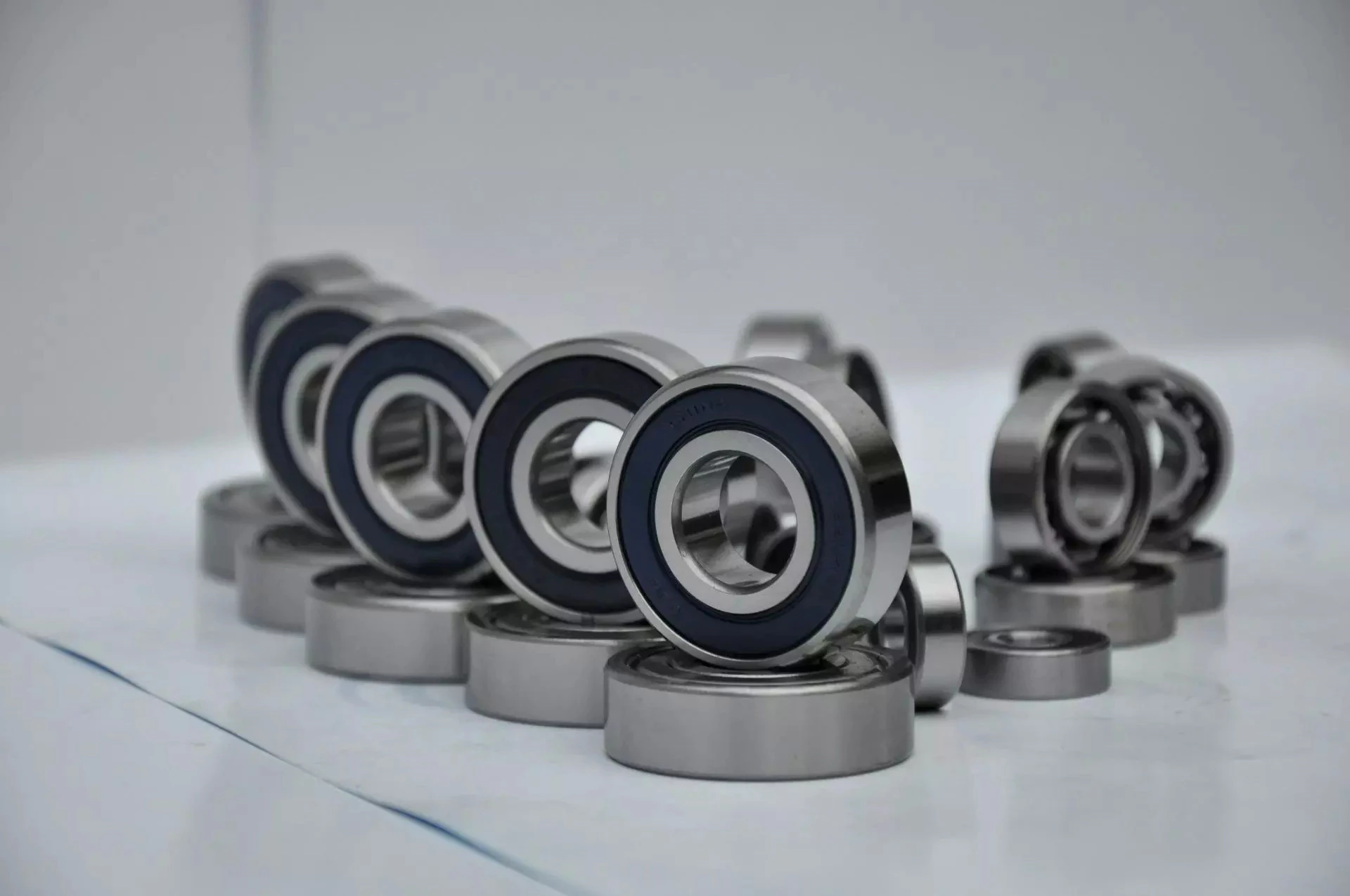
Single-row designs
Steel linear translation stages often use single-row designs for ball bearings. These types of bearings provide smooth linear travel and can withstand high loads. The material steel has a high modulus of elasticity and a high stiffness, as well as a lower thermal expansion than aluminum. For these reasons, steel is the material of choice for a ball bearing in a typical user environment. Single-row designs for ball bearings are also suitable for applications in humid or corrosive environments.
Single-row designs for ball bearings are available in a variety of sizes and are axially adjustable. They have a high radial capacity, but require relatively little space. Single-row deep groove ball bearings with snap rings are STN 02 4605 or R47, respectively. Bearings with snap rings are identified by a suffix such as NR. They may not have seals or shields installed.
These single-row angular contact ball bearings are capable of supporting axial and radial loads. In a two-raceway arrangement, the radial load on bearing A causes a radial load to act on bearing B. Both axial and radial forces are transmitted between single-row angular contact ball bearings, and the resulting internal force must be taken into account to calculate equivalent dynamic bearing loads P.
Single-row deep groove ball bearings are the most common type of ball bearings. These bearings are designed with only 1 row of rolling elements. The single-row design is simple and durable, which makes it ideal for high-speed applications. Single-row designs for ball bearings are also available in various bore sizes. They can also come in a variety of shapes and are non-separable. If you need a high-speed bearing, you may want to opt for a double-row design.
In addition to single-row designs for ball bearings, you can choose ceramic or steel ball bearings. Ceramic balls are considerably harder than steel balls, but they are not as hard as steel. Hence, ceramic bearings are stiffer than steel ball bearings, resulting in increased stress on the outer race groove and lower load capacity. This is a great benefit for those who need the bearings to be lightweight and strong.
The difference between single-row and double-row designs is in the way that the inner and outer ring are installed. A single-row design places the inner ring in an eccentric position relative to the outer ring. The 2 rings are in contact at 1 point, which causes a large gap in the bearing. The balls are then inserted through the gap. As a result, the balls are evenly distributed throughout the bearing, which forces the inner and outer rings to become concentric.
Deep-groove ball bearings are 1 of the most popular types of ball bearings. They are available in different designs, including snap-ring, seal and shield arrangements. The race diameter of a deep-groove ball bearing is close to the ball’s diameter. These types of bearings are suited for heavy loads, and their axial and radial support are excellent. Their main drawback is that the contact angle cannot be adjusted to accommodate a wide range of relative loads.
Ceramic hybrid ball bearings
Hybrid ball bearings with ceramic balls have numerous advantages. They feature improved kinematic behavior and require less lubrication. Consequently, they can reduce operating costs. Additionally, their low thermal expansion coefficient allows for smaller changes in contact angle and preload variations, and they can retain tolerances. Furthermore, ceramic hybrid ball bearings have significantly increased life spans compared to conventional steel-steel ball bearings, with up to 10 times the lifespan.
Although ceramic bearings can be used in automotive applications, many people believe that they’re a poor choice for bicycle hubs. They don’t reduce weight and only work well in high-rpm environments. As a result, many cyclists don’t even bother with ceramic-based bearings. However, both Paul Lew and Alan are of the opinion that ceramic bearings are best suited for industrial or medical equipment applications. Furthermore, Paul and Alan believe that they are ideal for high-altitude drone motors.
Another advantage of ceramic hybrid ball bearings is that they use less friction than conventional steel-based balls. They are also more durable, requiring less lubrication than steel-based bearings. Furthermore, the lower friction and rolling resistance associated with ceramic-based ball bearings means that they can last 10 times longer than steel-based bearings. A ceramic-based hybrid ball bearing can be used for applications where speed and lubrication are critical.
Ceramic hybrid ball bearings feature both steel and silicon nitride balls. Silicon nitride balls have 50% more modulus of elasticity than steel balls and can improve accuracy and precision. Ceramic balls also have a smoother surface finish than steel balls, which reduces vibration and spindle deflection. These benefits result in increased speed and improved production quality. In addition to this, ceramic balls can also reduce the operating temperature, enhancing the work environment.
Hybrid bearings are a popular alternative to steel bearings. They have some benefits over traditional steel bearings, and are becoming a popular choice for engineered applications. Hybrid bearings are ideal for high speed machines. The material used to manufacture ceramic balls is a high-quality alloy, and is comparatively inexpensive. But you must understand that lubrication is still necessary for hybrid bearings. If you are not careful, you may end up wasting money.
These ball bearings can be used in many industries and applications, and they are widely compatible with most metals. The main advantage of hybrid ball bearings is that they are very durable. While steel balls tend to corrode and wear out, ceramic ball bearings can withstand these conditions while minimizing maintenance and replacement costs. The benefits of hybrid ball bearings are clear. So, consider switching to these newer types of ball bearings.
Self-aligning ball bearings
Self-aligning ball bearings are a good choice for many applications. They are a great alternative to traditional ball bearings, and they are ideal for rotating applications in which the shaft must move in several directions. They are also ideal for use in rotating parts where a tight tolerance is necessary. You can choose between 2 types: plain and flex shaft. Read on to find out which 1 will suit your needs.
Self-aligning ball bearings are designed with a higher axial load carrying capacity than single-row radial deep groove ball bearings. The amount of axial load carrying capacity is dependent upon the pressure angle. These bearings have a hollow raceway in the outer ring that allows the inner ring to pivot without friction. They are often used for high-speed applications. Because of their design, they are highly accurate.
Self-aligning ball bearings are radial bearings that feature 2 rows of balls in a spherical outer ring. They also feature 2 deep uninterrupted raceway grooves in the inner ring. Their unique features make them an excellent choice for applications where shaft deflection is a significant factor. Despite their small size, they have a high level of precision and can withstand heavy loads.
Self-aligning ball bearings can compensate for misalignment in shaft applications. The inner ring and ball assembly are positioned inside an outer ring containing a curved raceway. This spherical design allows the balls and cage to deflect and re-align around the bearing center. These bearings are also ideal for applications where shaft deflection is significant, such as in simple woodworking machinery.
Another type of self-aligning ball bearing uses a common concave outer race. Both balls and outer races automatically compensate for angular misalignment caused by machining, assembly, and deflections. Compared to spherical rollers, they have lower frictional losses than their spherical counterparts. Self-alignment ball bearings also have lower vibration levels compared to other types of bearings.
Self-aligning ball bearings operate in misaligned applications because their spherical outer raceway can accommodate misalignment. This design allows them to work in applications where shaft deflection or housing deformation is common. They are therefore more suitable for low to medium-sized loads. The only real drawback to self-aligning ball bearings is their price. If you need to purchase a self-aligning ball bearing for your next project, you can expect to pay around $1500.
China high quality Agricultural 3 Point Hitch Tractor Pto Drive Flail Mower 15-45HP Tractor Small Mower with CE near me factory
Product Description
| MODEL | EFG105 | EFG115 | EFG125 | EFG135 |
| Structure Weight | 230kg | 245kg | 257kg | 272kg |
| Working Width | 1.02m | 1.12m | 1.22m | 1.32m |
| PTO Turning Speed | 540r/min | 540r/min | 540r/min | 540r/min |
| Flail Type | Y Blade/Hammer | |||
| Number of Flail | Y Blade:36 / Hammer:18 | Y Blade:36 / Hammer:18 | Y Blade:36 / Hammer:18 | Y Blade :44/ Hammer:22 |
| Tractor HP | 15-20hp | 15-20hp | 15-20hp | 18-25hp |
| MODEL | EFG145 | EFG155 | EFG165 | EFG175 |
| Structure Weight | 287kg | 302kg | 317kg | 329kg |
| Working Width | 1.42m | 1.52m | 1.62m | 1.72m |
| PTO Turning Speed | 540r/min | 540r/min | 540r/min | 540r/min |
| Flail Type | Y Blade/Hammer | |||
| Number of Flail | Y Blade :44/ Hammer:22 | Y Blade:44 / Hammer:22 | Y Blade:52/ Hammer:26 | Y Blade :52/ Hammer:26 |
| Tractor HP | 20-30hp | 20-30hp | 25-35hp | 30-35hp |
The EFG Series Flail Mower belongs to Medium Duty. Ideal for an orchard, nursery, vineyard, in the greenhouse or for gardening. With good blades and interchangeable blades, it is ideal for your ground maintenance. By putting on the Grass Mulching Blades you can maintain the grass area around your home, plus cut and mulch small twigs. If you need to maintain more dense areas, install the Hammer Blades and you will be CZPT to cut and mulch wooded material up to 2 inches in diameter.
HangZhou Qianyi Machinery Technology Co.,Ltd existing staff 50 people, in 2571 passed the ISO9001 quality system certification and passed CE certification.
Accumulated after years of development, we have many advanced equipment, like Germany fast Trulaser3030 laser cutting ,machine, CNC punch press TruPunch1000, CNC shearing machine, CNC lathe, bending machine, seam welding machine and more than 1 formula 1-160-1 high-end mechanical production equipment.
We provide good design, to help customers reduce costs of development and improve production efficiency. With complete testing equipment, strict quality control and abundant technical force, our machines are mainly exported to European, North American and Southeast Asian countries.
All of our machines are with 1 year warranty. We often insist on 1 principle”Better quality!Better service!Better price!”
What Are the Advantages of a Splined Shaft?
If you are looking for the right splined shaft for your machine, you should know a few important things. First, what type of material should be used? Stainless steel is usually the most appropriate choice, because of its ability to offer low noise and fatigue failure. Secondly, it can be machined using a slotting or shaping machine. Lastly, it will ensure smooth motion. So, what are the advantages of a splined shaft?
Stainless steel is the best material for splined shafts
When choosing a splined shaft, you should consider its hardness, quality, and finish. Stainless steel has superior corrosion and wear resistance. Carbon steel is another good material for splined shafts. Carbon steel has a shallow carbon content (about 1.7%), which makes it more malleable and helps ensure smooth motion. But if you’re not willing to spend the money on stainless steel, consider other options.
There are 2 main types of splines: parallel splines and crowned splines. Involute splines have parallel grooves and allow linear and rotary motion. Helical splines have involute teeth and are oriented at an angle. This type allows for many teeth on the shaft and minimizes the stress concentration in the stationary joint.
Large evenly spaced splines are widely used in hydraulic systems, drivetrains, and machine tools. They are typically made from carbon steel (CR10) and stainless steel (AISI 304). This material is durable and meets the requirements of ISO 14-B, formerly DIN 5463-B. Splined shafts are typically made of stainless steel or C45 steel, though there are many other materials available.
Stainless steel is the best material for a splined shaft. This metal is also incredibly affordable. In most cases, stainless steel is the best choice for these shafts because it offers the best corrosion resistance. There are many different types of splined shafts, and each 1 is suited for a particular application. There are also many different types of stainless steel, so choose stainless steel if you want the best quality.
For those looking for high-quality splined shafts, CZPT Spline Shafts offer many benefits. They can reduce costs, improve positional accuracy, and reduce friction. With the CZPT TFE coating, splined shafts can reduce energy and heat buildup, and extend the life of your products. And, they’re easy to install – all you need to do is install them.
They provide low noise, low wear and fatigue failure
The splines in a splined shaft are composed of 2 main parts: the spline root fillet and the spline relief. The spline root fillet is the most critical part, because fatigue failure starts there and propagates to the relief. The spline relief is more susceptible to fatigue failure because of its involute tooth shape, which offers a lower stress to the shaft and has a smaller area of contact.
The fatigue life of splined shafts is determined by measuring the S-N curve. This is also known as the Wohler curve, and it is the relationship between stress amplitude and number of cycles. It depends on the material, geometry and way of loading. It can be obtained from a physical test on a uniform material specimen under a constant amplitude load. Approximations for low-alloy steel parts can be made using a lower-alloy steel material.
Splined shafts provide low noise, minimal wear and fatigue failure. However, some mechanical transmission elements need to be removed from the shaft during assembly and manufacturing processes. The shafts must still be capable of relative axial movement for functional purposes. As such, good spline joints are essential to high-quality torque transmission, minimal backlash, and low noise. The major failure modes of spline shafts include fretting corrosion, tooth breakage, and fatigue failure.
The outer disc carrier spline is susceptible to tensile stress and fatigue failure. High customer demands for low noise and low wear and fatigue failure makes splined shafts an excellent choice. A fractured spline gear coupling was received for analysis. It was installed near the top of a filter shaft and inserted into the gearbox motor. The service history was unknown. The fractured spline gear coupling had longitudinally cracked and arrested at the termination of the spline gear teeth. The spline gear teeth also exhibited wear and deformation.
A new spline coupling method detects fault propagation in hollow cylindrical splined shafts. A spline coupling is fabricated using an AE method with the spline section unrolled into a metal plate of the same thickness as the cylinder wall. In addition, the spline coupling is misaligned, which puts significant concentration on the spline teeth. This further accelerates the rate of fretting fatigue and wear.
A spline joint should be lubricated after 25 hours of operation. Frequent lubrication can increase maintenance costs and cause downtime. Moreover, the lubricant may retain abrasive particles at the interfaces. In some cases, lubricants can even cause misalignment, leading to premature failure. So, the lubrication of a spline coupling is vital in ensuring proper functioning of the shaft.
The design of a spline coupling can be optimized to enhance its wear resistance and reliability. Surface treatments, loads, and rotation affect the friction properties of a spline coupling. In addition, a finite element method was developed to predict wear of a floating spline coupling. This method is feasible and provides a reliable basis for predicting the wear and fatigue life of a spline coupling.
They can be machined using a slotting or shaping machine
Machines can be used to shape splined shafts in a variety of industries. They are useful in many applications, including gearboxes, braking systems, and axles. A slotted shaft can be manipulated in several ways, including hobbling, broaching, and slotting. In addition to shaping, splines are also useful in reducing bar diameter.
When using a slotting or shaping machine, the workpiece is held against a pedestal that has a uniform thickness. The machine is equipped with a stand column and limiting column (Figure 1), each positioned perpendicular to the upper surface of the pedestal. The limiting column axis is located on the same line as the stand column. During the slotting or shaping process, the tool is fed in and out until the desired space is achieved.
One process involves cutting splines into a shaft. Straddle milling, spline shaping, and spline cutting are 2 common processes used to create splined shafts. Straddle milling involves a fixed indexing fixture that holds the shaft steady, while rotating milling cutters cut the groove in the length of the shaft. Several passes are required to ensure uniformity throughout the spline.
Splines are a type of gear. The ridges or teeth on the drive shaft mesh with grooves in the mating piece. A splined shaft allows the transmission of torque to a mate piece while maximizing the power transfer. Splines are used in heavy vehicles, construction, agriculture, and massive earthmoving machinery. Splines are used in virtually every type of rotary motion, from axles to transmission systems. They also offer better fatigue life and reliability.
Slotting or shaping machines can also be used to shape splined shafts. Slotting machines are often used to machine splined shafts, because it is easier to make them with these machines. Using a slotting or shaping machine can result in splined shafts of different sizes. It is important to follow a set of spline standards to ensure your parts are manufactured to the highest standards.
A milling machine is another option for producing splined shafts. A spline shaft can be set up between 2 centers in an indexing fixture. Two side milling cutters are mounted on an arbor and a spacer and shims are inserted between them. The arbor and cutters are then mounted to a milling machine spindle. To make sure the cutters center themselves over the splined shaft, an adjustment must be made to the spindle of the machine.
The machining process is very different for internal and external splines. External splines can be broached, shaped, milled, or hobbed, while internal splines cannot. These machines use hard alloy, but they are not as good for internal splines. A machine with a slotting mechanism is necessary for these operations.
China OEM 20-30HP Tractor Flail Mower CZPT Use Belt Pulley near me supplier
Product Description
Product Description
Specification:
1.3 point linkage
2. Graphite casting iron gearbox
3. Tractor power required: 18-30HP
4. With CE certificate
TM90-140: 48-21 sets in 20ft container, 96-43sets in 40ft container and 112-50 sets in 40HQ.
Production time: 22 -30 working days.
Description
Function
1. It is used for cutting higher weeds in the field, and also suitable for bushes or rougher weeds.
2. It cuts grass by high-speed operation and dead weight of blades.
Performance
1. Gearbox is made of graphite casting iron, with better material performance, not easy broken.
2. With adjustable rear wheel (option), it can prevent the body tail sinking, and the spacers above it can adjust the cutting height.
3. Blade spacers between up and down blade seat plates or connection plates can be replaced more easily after wearing, and the replacement cost will be smaller.
4. The improved model has more and denser blades to improve cutting efficiency, and the blades are thicker and heavier, not easy to break when meeting hard objects.
5. The machine is more durable and works more stably due to its heavier weight.
6. The blades are thicker, and the plates around has been strengthened. Two blades and 3 blades can be chosen according to different needs.
7. With front protection chain, it can prevent splashing.
8. Cat. I universal three-point hitch cardan shaft.
Company Introduction
HangZhou CZPT Industry & Trade Co., Ltd., is a professional manufacturer and exporter of whole set of farm machines and garden tools for 11 years, mainly including mowers, tillers, plows and Japanese tractor parts, etc.
We sincerely welcome customers abroad to visit us to discuss cooperation and seek common development. We believe our company is your most reliable partner and friend!
Machine Improvement
1. The old design was square with 2 blades, but now new design is disc with 3 blades. It has denser blades and can improve the cutting efficiency.
2. There were 5 holes on the wear plate before, but now there are 3 holes on the wear plate. It will be more convenient to replace them after improvement.
Company Overview
LEFA always invites foreign customers to visit company and test machinery. And it pays attention to the development of staff and provides abundant training for staff to improve ourselves.
Besides, CZPT insists on organizing staff to tour once a year and encourage staff to join more activities, to let us have an appointment with nature, enjoying the pleasure of life in our busy spare time.
FAQ
1. Trade terms: FOB, CIF, EXW
2. Sample Policy: You can test the quality of our sample firstly before you purchase them in mass quantity.
3. MOQ: 1 set
4. Payment Way: T/T, L/C, Western Union, D/P.
5. Delivery Date: 10-30 days after deposit paid. It depends on your order quantity.
6. Shipping Way: By Sea or By Air.
7. After Service: 12 months guarantee of the main parts, we will send the guarantee parts together with the machine in your next order or we can send them by air express if you need them urgently.
Types of Ball Bearings
There are many types of Ball Bearings available on the market, but which 1 is best for your application? Here, we will discuss the differences between Angular contact, Single-row, High-carbon steel, and Ceramic ball bearings. These types of bearings also feature races, or a groove in the center of each. These races are important in keeping the balls contained within the cylinder. They also provide a groove-baed pathway.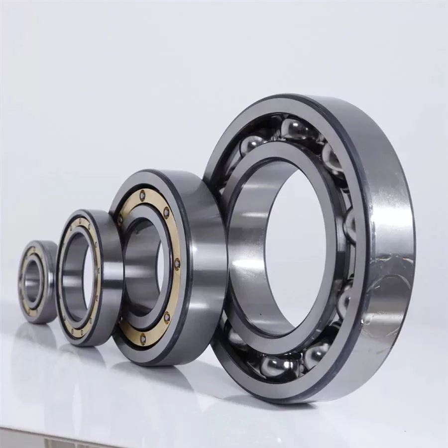
Ceramic
The ceramic ball used in ball bearings has many advantages. It is lightweight, operates at lower temperatures, has reduced skidding, and is resistant to electrolysis. The ball also exhibits longer fatigue life. All of these factors make the ceramic ball a good choice for many applications. But, how do you know if a ceramic ball bearing is right for your application? Read on to discover why ceramic ball bearings are a better choice than steel or stainless steel ones.
The ceramic balls are 40% more dense than steel. This means less centrifugal force is generated on the bearing, which suppresses heat generation. Because of this reduced friction, ceramic bearings are more efficient at transferring energy. Compared to steel bearings, ceramic balls have longer life spans. Nonetheless, these ceramic balls aren’t as strong as steel. Therefore, it is important to understand the limitations of the ceramic ball bearing before buying one.
The ceramic materials used for ball bearings are resistant to micro-welding. Metals undergo this process when imperfections in the surfaces interact. Eventually, this results in a brittle ball that reduces the life of a bearing. Unlike metals, ceramic materials have a stable behavior at high temperatures and exhibit less thermal expansion. This means that they can be used for applications where lubrication isn’t an option.
While steel balls can easily absorb contaminants and foreign particles, the ceramic ball is insensitive to this, and doesn’t require lubrication. This means they’re not susceptible to corrosion and other common problems. These are just a few reasons why ceramics are a better choice. This technology has a wide range of uses. It’s easy to see why it is so popular. If you’re looking for a new bearing for your application, be sure to contact an AST Applications Engineer. They can analyze your operating conditions and potential failure modes.
Angular contact
An Angular Contact Ball Bearing (also known as an angular-contact bearing) has an axial component that is generated when radial loads are applied. They are generally used in pairs, triplex sets, or quadruplex sets. These bearings are also available with Super Finished Raceways to reduce noise and improve lubricant distribution. Angular contact ball bearings have various design units, such as bore size, outer diameter, and outer ring width.
A single-row angular contact bearing has a radial contact angle that is equal to the angular distance between the 2 rings. Double-row angular bearings are designed for two-way thrust capability. These types of bearings can be purchased at Grainger and other online retailers. A typical angular contact bearing will last up to a million revolutions. They are often used in industrial angular contact bearings.
Single-row angular contact ball bearings feature a set contact angle. These bearings can support radial and axial loads, but they can’t withstand high speeds. Single-row angular contact ball bearings may also have 1 or 2 shoulders relieved. Thrust load is a pressure placed on the bearing when it is installed in an assembly, and it is used to create an angle between the races.
Angular contact ball bearings come in single and double-row configurations. They differ in the axial load they can carry and the type of lubrication they use. Angular contact ball bearings are ideal for high-speed applications and can accommodate both radial and axial loads. The type of contact and lubrication used in angular-contact ball bearings depends on the intended use for the bearing.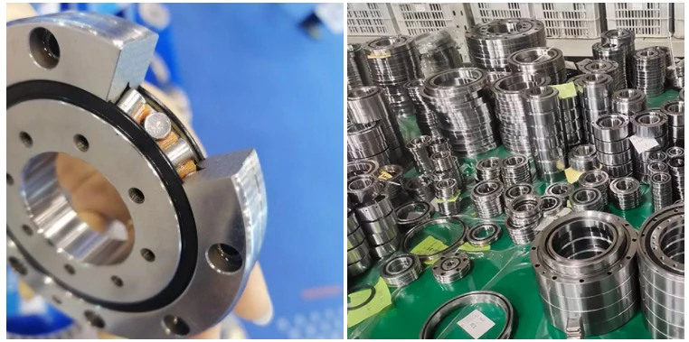
High-carbon steel
Carbon steel is a low-alloy and high-carbon steel used in bearings. This material provides superior strength and fatigue properties for ball and roller bearings. Its mechanical properties are ideal for applications where the temperature is less than 400 degrees Fahrenheit. High-carbon steel is also used to make bearing components for chrome steel bearings. These types of steels are softer than chrome steel but provide superior durability in applications where the material is exposed to severe conditions.
Hardened carbon steel balls with an AISI 1015 hardness index are used in a variety of automotive, commercial, and semi-precision applications. In addition to automotive applications, they are also used in slides, trolleys, and conveyors. AISI 1015 carbon steel balls are used in bearings. They can be purchased in a variety of weights and diameters. Carbon steel balls can also be purchased in nickel-plated or uncoated varieties for decorative purposes.
In order to determine whether a ball bearing is made of high-carbon steel, the material must be tested for its hardness. An ordinary pocket magnet will work well, but an ordinary rare earth magnet isn’t powerful enough to measure the hardness. If it attracts the magnet strongly, the metal is steel, while a weak magnet indicates a non-ferrous material. A hardness test requires a special microhardness test.
A lower-carbon steel is another option. Some miniature bearing manufacturers use a material with less carbon than AISI 440C. This material is also known as KS440 or X65Cr13. After being heat-treated, it develops smaller carbides, resulting in superior low-noise characteristics and the same corrosion-resistance as 440C. These materials are a less expensive alternative than chrome steel, but they are often less durable than chrome alloy steel.
Single-row
Single-row angular contact ball bearings accommodate axial loads in 1 direction. These are normally adjusted against a second bearing. Unlike other ball bearings, they are non-separable and contain an upper and lower shoulder. Single-row ball bearings are made of Chromium Steel (GCr15) which is heat-treated to achieve high uniform hardness and excellent wear resistance. They are the most commonly used type of bearings in the world.
Because of the angular contact between the radial plane and the raceway, single-row ball bearings transmit radial forces from raceway to raceway. A higher a, the greater the axial load carrying capacity of the bearing. Single-row angular contact ball bearings are ideal for high axial loads. However, they have limited preload capabilities and must be installed in pairs. Hence, they are best used for applications where axial forces must be distributed.
Single-row ball bearings can be pre-lubricated and have steel shields. They are also available with rubber seals or snap rings on the outside edge. They are available with various retainers, including pressed steel cages, plastic shields, and rubber seals. A tapered bore is also available upon request. They are ideal for applications where space is limited. The 6200 series of bearings are especially well suited for electrical motors, dental hand tools, and optical encoders.
Single-row angular contact ball bearings are widely used for axial loads. The outer and inner rings have slightly larger radii than the balls. These bearings can accommodate high speeds and low torque. They can also be supplied with different grease levels. If grease is needed, you can choose a lubricant that has different characteristics depending on the application. They are easy to install and maintain. However, they are not recommended for adjacent mounting.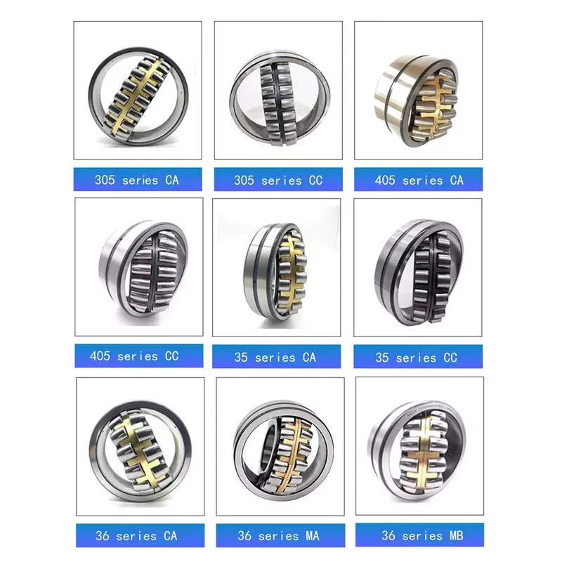
Plastic
A plastic ball bearing is a highly versatile component that can be mounted in a variety of components, including wheels, pulleys and housings. The outer ring of a plastic bearing is usually the pulley profile. The inner ring can be made of a shaft or polymer. The integrated design of a plastic ball bearing helps to reduce assembly time and cost. Here are some of the benefits of this type of bearing:
First and foremost, plastic balls are lighter than metal balls. They also have less magnetic properties than steel balls, making them the best option for applications requiring low weight and noise. Glass balls are also lighter than stainless steel balls, making them the ideal metal-free choice. They are also very corrosion-resistant, which makes them a great choice for some applications. In addition to being lightweight, polymer ball bearings are also quiet. And because of their low weight, plastic ball bearings are ideal for applications that require fast speed.
Another advantage of plastic bearings is their ability to withstand high temperatures. This material is also abrasion and corrosion-resistant. It meets FDA and USDA acceptance requirements. Aside from its abrasion-resistant and corrosion-resistant properties, these plastics do not transfer heat. Aside from being extremely durable and flexible, most plastics are also self-lubricating. Common plastics include phenolics, acetals, nylon, and ultra high molecular weight polyethylene. Nonetheless, plastics have limitations, and these materials may be damaged by extreme temperatures or cold flow under heavy loads.
Other advantages of plastic ball bearings include their low density, high hardness and low friction coefficient, and ability to withstand heat and corrosion. Ceramics are also lightweight, non-conductive, and have superior resistance to friction. These products can withstand temperatures up to 1,800 degrees Fahrenheit. If you’re in the market for a plastic ball bearing, it’s important to choose the right type of material. And if you’re looking for a high-quality bearing, look no further.
China Professional Tractor Mounted 3 Point Linkage Light Duty Flail Mower with Movable Gearbox with Good quality
Product Description
Product Specifications:
| Model | TLS85 | TLS95 | TLS105 | TLS115 | TLS125 | TLS135 |
| Weight | 155kg | 175kg | 195kg | 215kg | 326kg | 358kg |
| Tilling Width | 800mm | 900mm | 1000mm | 1100mm | 1200mm | 1300mm |
| Tilling Depth | 90mm | |||||
| No. Of Blade | 20 | 20 | 24 | 24 | 28 | 28 |
| PTO Turning Speed | 540r/min | |||||
| Tractor HP | 12-20hp | 12-20hp | 15-22hp | 18-22hp | 18-22hp | |
Product Description:
Light weight rotary tiller for compact tractors 15-30hp.
It is used for small farms, fruit and vegetables, orchards, gardening and nurseries.Suitable for soil conditioning and weed control, seedbed preparation, puddling in small fields.It is compatible for mini and lower HP tractor.
Can loosen & aerate soil 4 to 5 inches deep.
Our advantages:
A whole complete set of production equipment lead to short lead time and better prices of machine.
Guarantee 1 year warranty of all our products.
Produce machines according to any requirements from our customers.
New machines will be developed every year.
Every model of our machine will be tested before the delivery to the port.
If you want to visit our factory, our boss will give you a best reception.
Beautiful gifts will be provided for all of our customers before every year’s Christmas.
Work shop and office:
Welding:
Blade shaft:
Laser equipment:
Office:
Rest place:
Assembly:
Finished machines:
CNC:
Agricultural Parts
If you’ve been to a farm, you’ve probably seen all kinds of agricultural parts. These mechanical devices are used in agriculture and include hand tools, power tools, tractors and countless farm implements. If you’re not familiar with them, it’s time to review them. Read on to learn more about agricultural parts. Of course, if you’re looking for specific types, you’ll want to know what makes them different.
Steel
Modern farmers demand greater productivity and efficiency, lower fuel and other costs. Forged steel is 1 solution that meets both of these goals. With forged steel agricultural parts, the future of agriculture is bright. In this article, we’ll review some of the key steels used in agricultural equipment and their unique properties. Ultimately, you’ll save money and increase productivity. let’s start. How do steel agricultural parts work?
Steel is corrosion resistant. It can withstand the corrosive elements that agricultural equipment encounters in the field. Steel is also ductile, allowing for design flexibility. Because of these advantages, steel is the first choice for farm and hand tools. Steel also prevents soil from sticking, making cleanup easier. Stainless steel is 100% recyclable and may have antimicrobial properties. In addition to being resistant to corrosion, steel retains its integrity in outdoor conditions.
In addition to the quality of steel agricultural components, it is also important to choose a responsible manufacturer. Whether a company is responsible for the money or just for the money depends on the product the manufacturer offers. Some manufacturers may lack reputational advantages or have workmanship defects. Therefore, it is necessary to pay attention to certain aspects in the production process of steel farming accessories manufacturers.
Iron
Cast iron components for agricultural machinery are extremely durable and strong, and are manufactured to meet the needs of leading agricultural machinery manufacturers. They are available in a variety of shapes and weights and can also be customized to meet specific customer requirements. Here are some common uses for iron agricultural parts. Read on to learn about their capabilities and how they can benefit you. Agricultural iron parts are widely used in agricultural equipment such as tractors, combine harvesters, and combine harvesters. Agricultural machinery such as tractors, weeders and harvesters require iron components. Grey cast iron, cast steel and ductile iron are commonly used materials for agricultural machinery parts. The grey cast iron gearbox supports the drive shaft and ensures the correct installation of other components. Grey cast iron has excellent wear resistance and machinability, and also has a damping effect. Below are some common examples of gray iron agricultural machinery parts.
Aluminium
Some of the leading companies in the agricultural industry choose to use aluminium components in their equipment. CZPT is 1 of these companies. With more than 50 years of experience in the aluminum industry, the company has brought many innovations to the agricultural market. I recently had the opportunity to speak with Jonas Bjuhr, Director of Product Development at CZPT. He shares his insights on agricultural aluminum solutions and his philosophy on how the company does business.
Metal spinning process, also known as spinning and metal turning, is the transformation of metal cylindrical parts into hollow parts. The process works with a variety of metal bases, producing parts that are both strong and durable. Chicago Metal Company has been producing agricultural equipment parts since 1908. It is also known for producing straight seam lock seam irrigation pipes. To deliver the pipes, Chicago Metals will load railcars on the siding at its plant. However, the rise of PVC pipes has made this process unnecessary. The company has developed standard angle flange connection pipes.
Bronze
Bronze is a metal alloy composed of copper and tin. As an alloy, it binds 2 metals together at the molecular level to form a new material. Although people throughout history don’t know why tin and copper were combined to make bronze, an innovative blacksmith discovered the alloy and opened up new possibilities. Bronze agricultural parts are made from a variety of metals, including copper and tin. Below are some common examples.
Plants found at the Raj site are mainly fruit crops, but the archaeological site also includes large amounts of barley and emmer. The lack of chaff suggests that grain processing took place far from the site, suggesting that fruit crops played an important role in the agricultural life of the Raj in the 15th and 12th centuries BC. However, there is very little information on how the grain is processed.
Late Bronze Age sites have cadaveric remains of grains and legumes, but no new crops have been found. In the Iberian region, CZPT is more prominent, while other legumes are less common. Acorns are the only wild fruit consistently found at archaeological sites, suggesting their role in regional survival. The earliest recorded use of pits as storage facilities lasts at least 4,000 years.
Cast iron
CZPT manufactures cast iron agricultural parts that provide strength and durability to a wide variety of agricultural machinery. They meet the exacting specifications of leading agricultural machinery manufacturers, ensuring a reliable product in the field. The company offers a variety of weights and shapes, and can customize solutions for any application. Below are some of the most popular applications for cast iron agricultural parts. Each of these applications offers a range of advantages. The company’s engineers provide state-of-the-art technical solutions.
Cast iron products have a variety of uses in the construction and mining industries. These metals are used to build bridges, building frames, lamp posts, gates, and more. These metals also make excellent engineering materials for water pipes and sewers, manhole covers, and more. Below are some of the most common applications for cast iron agricultural parts. To learn more about the many applications of cast iron agricultural components, visit the university.
Aluminium alloy
If you are interested in replacing metal agricultural parts, consider the advantages of aluminium alloys. Not only is it lightweight, it is also non-corrosive and non-corrosive, making it a perfect replacement for heavier metals. And it’s also better for the environment, which is a growing concern. Learn what you can do with aluminum castings and why you should use them for your agricultural components. We can help you find the right alloy for the application and specific application you are using.
Aluminum alloys are available in different grades, which are further divided into various properties. Different grades are classified according to the main alloy composition. Alloys are selected based on their strength-to-weight ratio and other factors. In addition, they have high levels of ductility, workability and corrosion resistance. Because of these properties, aluminum alloys are widely used in aircraft and many other industrial applications.
Bronze Alloys
One of the most common uses of bronze alloys is in agricultural parts. Its copper-tin composition provides strength and durability. This alloy is also corrosion resistant. Many farmers use bronze for agricultural purposes, especially combine harvesters and other tools. The following article will describe the benefits of bronze in agricultural uses. Read on to learn more. The basic structure of bronze alloys is as follows. Bronze is composed of 88% copper and 12% tin. The ratio of tin increases with melting, while the ratio of copper to tin decreases.
This copper-based metal has unique properties that are indistinguishable by appearance alone. You should look for a metal specialist who can guide you to find the best fit for your needs. CZPT is 1 of the top copper suppliers and they manufacture their own products. The metal spinning process is the most versatile and consistent method of manufacturing parts. Bronze is a product of adding tin to copper and has many positive properties.
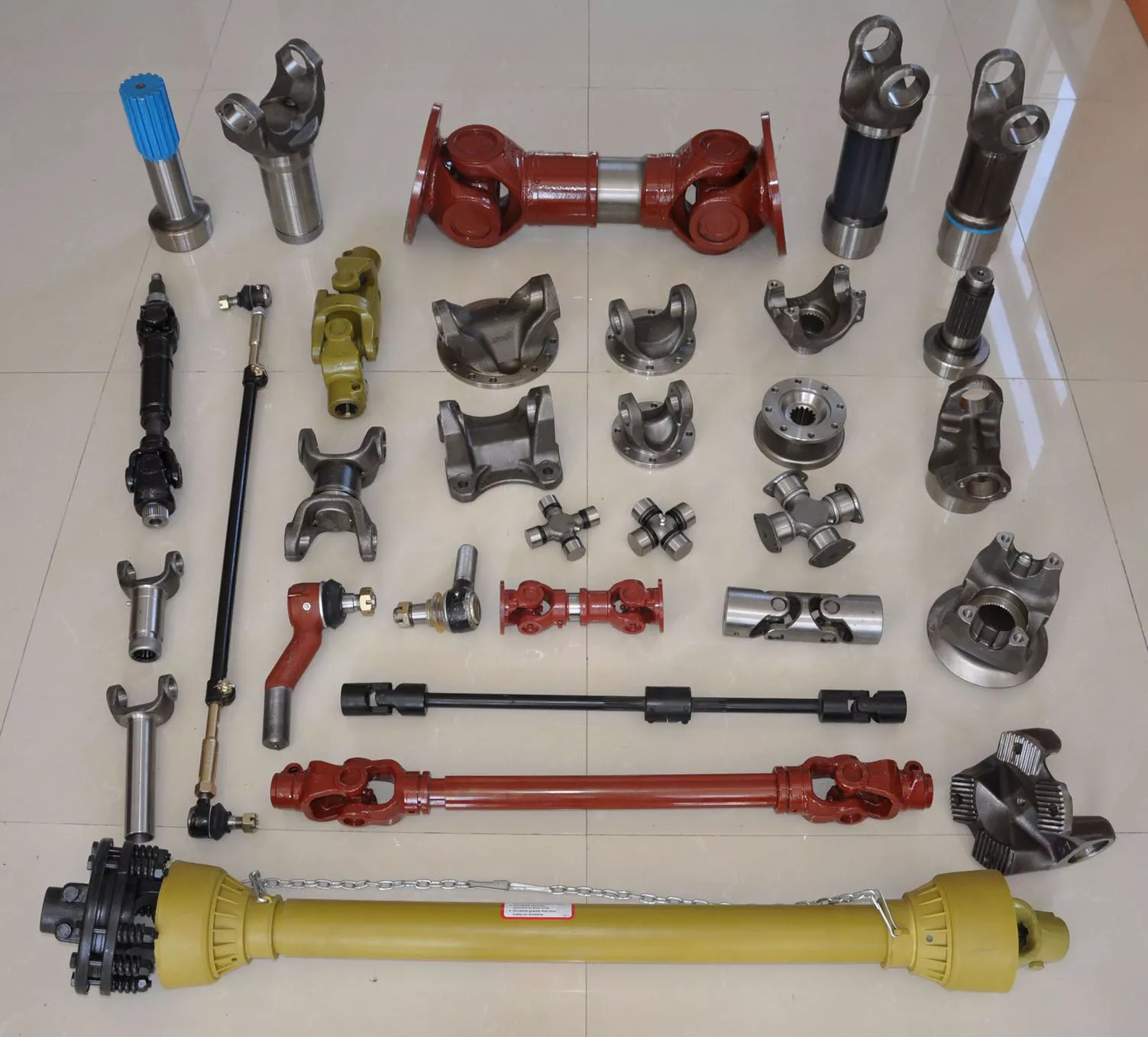
Cast Iron Alloys
CZPT provides rugged cast iron agricultural components for a variety of applications. These castings are manufactured to the exacting requirements of leading agricultural machinery manufacturers, ensuring a reliable product in the field. Their castings come in a variety of shapes and weights and can also be custom designed to meet individual customer requirements. The application of cast iron includes:
Ductile iron, also known as ductile iron, is a special property obtained by adding magnesium to the metal. It is a ductile iron that is spherical due to the addition of magnesium. In the manufacturing process, composition control is important because impurities such as sulfur and oxygen react with magnesium to form different types of ductile iron. These impurities change the shape of the graphite molecules. Different grades of ductile iron are obtained by manipulating the microcrystalline structure of the metal, making austempered ductile iron another type of cast iron.
This ferrite-containing iron is suitable for machining. Its microstructure is similar to mild steel, but it contains enough dissolved silicon to remove the metal’s stickiness. This means that ferritic cast iron castings do not require the addition of sulphur or lead. If high-speed machining is used, false chips will form on the cutting edge. However, the machinability of cast iron makes it an excellent choice for agricultural applications.
What makes agricultural parts so special?
If you’ve been to a farm, you’ve probably seen all kinds of agricultural parts. These mechanical devices are used in agriculture and include hand tools, power tools, tractors and countless farm implements. If you’re not familiar with them, it’s time to review them. Read on to learn more about agricultural parts. Of course, if you’re looking for specific types, you’ll want to know what makes them different.
Steel
Modern farmers demand greater productivity and efficiency, lower fuel and other costs. Forged steel is 1 solution that meets both of these goals. With forged steel agricultural parts, the future of agriculture is bright. In this article, we’ll review some of the key steels used in agricultural equipment and their unique properties. Ultimately, you’ll save money and increase productivity. let’s start. How do steel agricultural parts work?
Steel is corrosion resistant. It can withstand the corrosive elements that agricultural equipment encounters in the field. Steel is also ductile, allowing for design flexibility. Because of these advantages, steel is the first choice for farm and hand tools. Steel also prevents soil from sticking, making cleanup easier. Stainless steel is 100% recyclable and may have antimicrobial properties. In addition to being resistant to corrosion, steel retains its integrity in outdoor conditions.
In addition to the quality of steel agricultural components, it is also important to choose a responsible manufacturer. Whether a company is responsible for the money or just for the money depends on the product the manufacturer offers. Some manufacturers may lack reputational advantages or have workmanship defects. Therefore, it is necessary to pay attention to certain aspects in the production process of steel agricultural accessories manufacturers.
China Best Sales Agriculture Farm Mower Tractor Linkage Grass Toppers Weed Cutter with Hot selling
Product Description
Product Description
Specification:
1.3 point linkage
2. Graphite casting iron gearbox
3. Tractor power required: 18-30HP
4. With CE certificate
TM90-140: 48-21 sets in 20ft container, 96-43sets in 40ft container and 112-50 sets in 40HQ.
Production time: 22 -30 working days.
Description
Function
1. It is used for cutting higher weeds in the field, and also suitable for bushes or rougher weeds.
2. It cuts grass by high-speed operation and dead weight of blades.
Performance
1. Gearbox is made of graphite casting iron, with better material performance, not easy broken.
2. With adjustable rear wheel (option), it can prevent the body tail sinking, and the spacers above it can adjust the cutting height.
3. Blade spacers between up and down blade seat plates or connection plates can be replaced more easily after wearing, and the replacement cost will be smaller.
4. The improved model has more and denser blades to improve cutting efficiency, and the blades are thicker and heavier, not easy to break when meeting hard objects.
5. The machine is more durable and works more stably due to its heavier weight.
6. The blades are thicker, and the plates around has been strengthened. Two blades and 3 blades can be chosen according to different needs.
7. With front protection chain, it can prevent splashing.
8. Cat. I universal three-point hitch cardan shaft.
Company Introduction
HangZhou CZPT Industry & Trade Co., Ltd., is a professional manufacturer and exporter of whole set of farm machines and garden tools for 11 years, mainly including mowers, tillers, plows and Japanese tractor parts, etc.
We sincerely welcome customers abroad to visit us to discuss cooperation and seek common development. We believe our company is your most reliable partner and friend!
Machine Improvement
1. The old design was square with 2 blades, but now new design is disc with 3 blades. It has denser blades and can improve the cutting efficiency.
2. There were 5 holes on the wear plate before, but now there are 3 holes on the wear plate. It will be more convenient to replace them after improvement.
Company Overview
LEFA always invites foreign customers to visit company and test machinery. And it pays attention to the development of staff and provides abundant training for staff to improve ourselves.
Besides, CZPT insists on organizing staff to tour once a year and encourage staff to join more activities, to let us have an appointment with nature, enjoying the pleasure of life in our busy spare time.
FAQ
1. Trade terms: FOB, CIF, EXW
2. Sample Policy: You can test the quality of our sample firstly before you purchase them in mass quantity.
3. MOQ: 1 set
4. Payment Way: T/T, L/C, Western Union, D/P.
5. Delivery Date: 10-30 days after deposit paid. It depends on your order quantity.
6. Shipping Way: By Sea or By Air.
7. After Service: 12 months guarantee of the main parts, we will send the guarantee parts together with the machine in your next order or we can send them by air express if you need them urgently.
How to Select a Worm Shaft and Gear For Your Project
You will learn about axial pitch PX and tooth parameters for a Worm Shaft 20 and Gear 22. Detailed information on these 2 components will help you select a suitable Worm Shaft. Read on to learn more….and get your hands on the most advanced gearbox ever created! Here are some tips for selecting a Worm Shaft and Gear for your project!…and a few things to keep in mind.
Gear 22
The tooth profile of Gear 22 on Worm Shaft 20 differs from that of a conventional gear. This is because the teeth of Gear 22 are concave, allowing for better interaction with the threads of the worm shaft 20. The worm’s lead angle causes the worm to self-lock, preventing reverse motion. However, this self-locking mechanism is not entirely dependable. Worm gears are used in numerous industrial applications, from elevators to fishing reels and automotive power steering.
The new gear is installed on a shaft that is secured in an oil seal. To install a new gear, you first need to remove the old gear. Next, you need to unscrew the 2 bolts that hold the gear onto the shaft. Next, you should remove the bearing carrier from the output shaft. Once the worm gear is removed, you need to unscrew the retaining ring. After that, install the bearing cones and the shaft spacer. Make sure that the shaft is tightened properly, but do not over-tighten the plug.
To prevent premature failures, use the right lubricant for the type of worm gear. A high viscosity oil is required for the sliding action of worm gears. In two-thirds of applications, lubricants were insufficient. If the worm is lightly loaded, a low-viscosity oil may be sufficient. Otherwise, a high-viscosity oil is necessary to keep the worm gears in good condition.
Another option is to vary the number of teeth around the gear 22 to reduce the output shaft’s speed. This can be done by setting a specific ratio (for example, 5 or 10 times the motor’s speed) and modifying the worm’s dedendum accordingly. This process will reduce the output shaft’s speed to the desired level. The worm’s dedendum should be adapted to the desired axial pitch.
Worm Shaft 20
When selecting a worm gear, consider the following things to consider. These are high-performance, low-noise gears. They are durable, low-temperature, and long-lasting. Worm gears are widely used in numerous industries and have numerous benefits. Listed below are just some of their benefits. Read on for more information. Worm gears can be difficult to maintain, but with proper maintenance, they can be very reliable.
The worm shaft is configured to be supported in a frame 24. The size of the frame 24 is determined by the center distance between the worm shaft 20 and the output shaft 16. The worm shaft and gear 22 may not come in contact or interfere with 1 another if they are not configured properly. For these reasons, proper assembly is essential. However, if the worm shaft 20 is not properly installed, the assembly will not function.
Another important consideration is the worm material. Some worm gears have brass wheels, which may cause corrosion in the worm. In addition, sulfur-phosphorous EP gear oil activates on the brass wheel. These materials can cause significant loss of load surface. Worm gears should be installed with high-quality lubricant to prevent these problems. There is also a need to choose a material that is high-viscosity and has low friction.
Speed reducers can include many different worm shafts, and each speed reducer will require different ratios. In this case, the speed reducer manufacturer can provide different worm shafts with different thread patterns. The different thread patterns will correspond to different gear ratios. Regardless of the gear ratio, each worm shaft is manufactured from a blank with the desired thread. It will not be difficult to find 1 that fits your needs.
Gear 22’s axial pitch PX
The axial pitch of a worm gear is calculated by using the nominal center distance and the Addendum Factor, a constant. The Center Distance is the distance from the center of the gear to the worm wheel. The worm wheel pitch is also called the worm pitch. Both the dimension and the pitch diameter are taken into consideration when calculating the axial pitch PX for a Gear 22.
The axial pitch, or lead angle, of a worm gear determines how effective it is. The higher the lead angle, the less efficient the gear. Lead angles are directly related to the worm gear’s load capacity. In particular, the angle of the lead is proportional to the length of the stress area on the worm wheel teeth. A worm gear’s load capacity is directly proportional to the amount of root bending stress introduced by cantilever action. A worm with a lead angle of g is almost identical to a helical gear with a helix angle of 90 deg.
In the present invention, an improved method of manufacturing worm shafts is described. The method entails determining the desired axial pitch PX for each reduction ratio and frame size. The axial pitch is established by a method of manufacturing a worm shaft that has a thread that corresponds to the desired gear ratio. A gear is a rotating assembly of parts that are made up of teeth and a worm.
In addition to the axial pitch, a worm gear’s shaft can also be made from different materials. The material used for the gear’s worms is an important consideration in its selection. Worm gears are usually made of steel, which is stronger and corrosion-resistant than other materials. They also require lubrication and may have ground teeth to reduce friction. In addition, worm gears are often quieter than other gears.
Gear 22’s tooth parameters
A study of Gear 22’s tooth parameters revealed that the worm shaft’s deflection depends on various factors. The parameters of the worm gear were varied to account for the worm gear size, pressure angle, and size factor. In addition, the number of worm threads was changed. These parameters are varied based on the ISO/TS 14521 reference gear. This study validates the developed numerical calculation model using experimental results from Lutz and FEM calculations of worm gear shafts.
Using the results from the Lutz test, we can obtain the deflection of the worm shaft using the calculation method of ISO/TS 14521 and DIN 3996. The calculation of the bending diameter of a worm shaft according to the formulas given in AGMA 6022 and DIN 3996 show a good correlation with test results. However, the calculation of the worm shaft using the root diameter of the worm uses a different parameter to calculate the equivalent bending diameter.
The bending stiffness of a worm shaft is calculated through a finite element model (FEM). Using a FEM simulation, the deflection of a worm shaft can be calculated from its toothing parameters. The deflection can be considered for a complete gearbox system as stiffness of the worm toothing is considered. And finally, based on this study, a correction factor is developed.
For an ideal worm gear, the number of thread starts is proportional to the size of the worm. The worm’s diameter and toothing factor are calculated from Equation 9, which is a formula for the worm gear’s root inertia. The distance between the main axes and the worm shaft is determined by Equation 14.
Gear 22’s deflection
To study the effect of toothing parameters on the deflection of a worm shaft, we used a finite element method. The parameters considered are tooth height, pressure angle, size factor, and number of worm threads. Each of these parameters has a different influence on worm shaft bending. Table 1 shows the parameter variations for a reference gear (Gear 22) and a different toothing model. The worm gear size and number of threads determine the deflection of the worm shaft.
The calculation method of ISO/TS 14521 is based on the boundary conditions of the Lutz test setup. This method calculates the deflection of the worm shaft using the finite element method. The experimentally measured shafts were compared to the simulation results. The test results and the correction factor were compared to verify that the calculated deflection is comparable to the measured deflection.
The FEM analysis indicates the effect of tooth parameters on worm shaft bending. Gear 22’s deflection on Worm Shaft can be explained by the ratio of tooth force to mass. The ratio of worm tooth force to mass determines the torque. The ratio between the 2 parameters is the rotational speed. The ratio of worm gear tooth forces to worm shaft mass determines the deflection of worm gears. The deflection of a worm gear has an impact on worm shaft bending capacity, efficiency, and NVH. The continuous development of power density has been achieved through advancements in bronze materials, lubricants, and manufacturing quality.
The main axes of moment of inertia are indicated with the letters A-N. The three-dimensional graphs are identical for the seven-threaded and one-threaded worms. The diagrams also show the axial profiles of each gear. In addition, the main axes of moment of inertia are indicated by a white cross.